2 CONTROLS AND CONNECTORS
|
|
|
|
|
|
| MIC | VIDEO | AUDIO |
|
|
|
|
|
|
| IN |
| |
|
|
|
|
|
|
|
|
| |
|
|
|
|
|
|
|
| IN | IN |
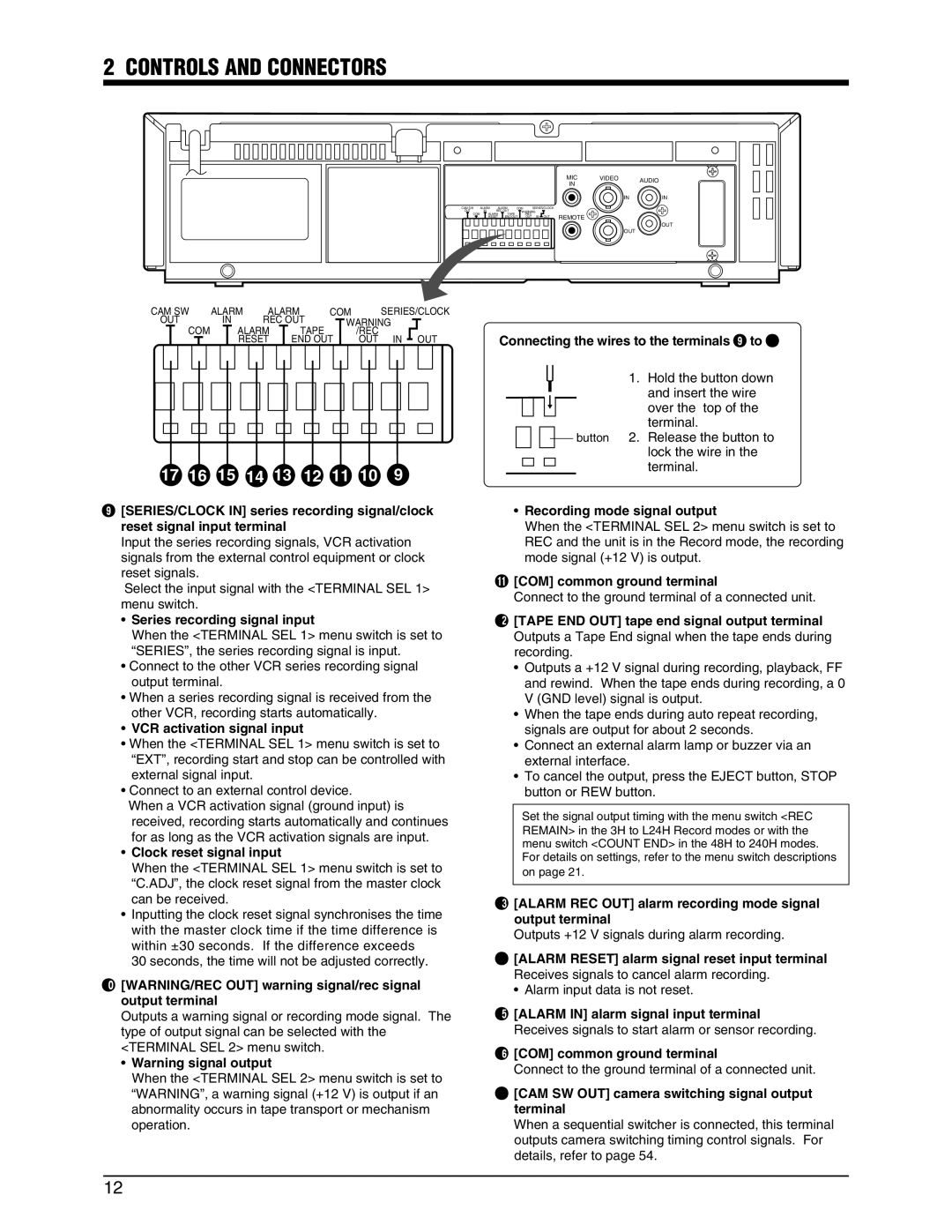
CAM SW | ALARM | ALARM | COM |
| SERIES/CLOCK |
|
|
| |
OUT | IN | REC OUT | WARNING |
|
|
| |||
COM | ALARM | TAPE |
| /REC |
| REMOTE |
|
| |
| RESET | END OUT | OUT | IN OUT |
|
| |||
OUT
OUT
CAM SW | ALARM |
|
| ALARM | COM |
|
|
|
| SERIES/CLOCK | |||||||||||||||||||||||||||||||||||||
| OUT |
| IN |
|
| REC | OUT |
|
|
| WARNING |
|
|
|
|
|
| ||||||||||||||||||||||||||||||
|
|
|
|
|
|
|
|
| |||||||||||||||||||||||||||||||||||||||
|
|
|
|
|
| COM |
|
|
|
| ALARM |
|
|
|
| TAPE |
|
|
|
|
| /REC |
|
|
|
|
|
|
|
|
|
| |||||||||||||||
|
|
|
|
|
|
|
|
|
|
|
|
|
|
|
|
|
|
|
| ||||||||||||||||||||||||||||
|
|
|
|
|
|
|
|
|
|
|
|
|
|
| RESET |
|
| END OUT |
|
|
| OUT |
| IN | OUT | ||||||||||||||||||||||
|
|
|
|
|
|
|
|
|
|
|
|
|
|
|
|
| |||||||||||||||||||||||||||||||
|
|
|
|
|
|
|
|
|
|
|
|
|
|
|
|
|
|
|
|
|
|
|
|
|
|
|
|
|
|
|
|
|
|
|
|
|
|
|
|
|
|
|
|
|
|
|
|
|
|
|
|
|
|
|
|
|
|
|
|
|
|
|
|
|
|
|
|
|
|
|
|
|
|
|
|
|
|
|
|
|
|
|
|
|
|
|
|
|
|
|
|
|
|
|
|
|
|
|
|
|
|
|
|
|
|
|
|
|
|
|
|
|
|
|
|
|
|
|
|
|
|
|
|
|
|
|
|
|
|
|
|
|
|
|
|
|
|
|
|
|
|
|
|
|
|
|
|
|
|
|
|
|
|
|
|
|
|
|
|
|
|
|
|
|
|
|
|
|
|
|
|
|
|
|
|
|
|
|
|
|
|
|
|
|
|
|
|
|
|
|
|
|
|
|
|
|
|
|
|
|
|
|
|
|
|
|
|
|
|
|
|
|
|
|
|
|
|
|
|
|
|
|
|
|
|
|
|
|
|
|
|
|
|
|
|
|
|
|
|
|
|
|
|
|
|
|
|
|
|
|
|
|
|
|
|
|
|
|
|
|
|
|
|
|
|
|
|
|
|
|
|
|
|
|
|
|
|
|
|
|
|
|
|
|
|
|
|
17 | 16 | 15 | 14 | 13 | 12 | 11 | 10 | 9 |
9[SERIES/CLOCK IN] series recording signal/clock reset signal input terminal
Input the series recording signals, VCR activation signals from the external control equipment or clock reset signals.
Select the input signal with the <TERMINAL SEL 1> menu switch.
•Series recording signal input
When the <TERMINAL SEL 1> menu switch is set to “SERIES”, the series recording signal is input.
•Connect to the other VCR series recording signal output terminal.
•When a series recording signal is received from the other VCR, recording starts automatically.
•VCR activation signal input
•When the <TERMINAL SEL 1> menu switch is set to “EXT”, recording start and stop can be controlled with external signal input.
•Connect to an external control device.
When a VCR activation signal (ground input) is received, recording starts automatically and continues for as long as the VCR activation signals are input.
•Clock reset signal input
When the <TERMINAL SEL 1> menu switch is set to “C.ADJ”, the clock reset signal from the master clock can be received.
•Inputting the clock reset signal synchronises the time with the master clock time if the time difference is within ±30 seconds. If the difference exceeds
30 seconds, the time will not be adjusted correctly.
0[WARNING/REC OUT] warning signal/rec signal output terminal
Outputs a warning signal or recording mode signal. The type of output signal can be selected with the <TERMINAL SEL 2> menu switch.
•Warning signal output
When the <TERMINAL SEL 2> menu switch is set to “WARNING”, a warning signal (+12 V) is output if an abnormality occurs in tape transport or mechanism operation.
Connecting the wires to the terminals 9 to &
1. Hold the button down and insert the wire over the top of the terminal.
![]() button 2. Release the button to lock the wire in the terminal.
button 2. Release the button to lock the wire in the terminal.
•Recording mode signal output
When the <TERMINAL SEL 2> menu switch is set to REC and the unit is in the Record mode, the recording mode signal (+12 V) is output.
![COM] common ground terminal
Connect to the ground terminal of a connected unit.
@[TAPE END OUT] tape end signal output terminal Outputs a Tape End signal when the tape ends during recording.
•Outputs a +12 V signal during recording, playback, FF and rewind. When the tape ends during recording, a 0 V (GND level) signal is output.
•When the tape ends during auto repeat recording, signals are output for about 2 seconds.
•Connect an external alarm lamp or buzzer via an external interface.
•To cancel the output, press the EJECT button, STOP button or REW button.
Set the signal output timing with the menu switch <REC REMAIN> in the 3H to L24H Record modes or with the menu switch <COUNT END> in the 48H to 240H modes. For details on settings, refer to the menu switch descriptions on page 21.
#[ALARM REC OUT] alarm recording mode signal output terminal
Outputs +12 V signals during alarm recording.
$[ALARM RESET] alarm signal reset input terminal Receives signals to cancel alarm recording.
• Alarm input data is not reset.
%[ALARM IN] alarm signal input terminal Receives signals to start alarm or sensor recording.
^[COM] common ground terminal
Connect to the ground terminal of a connected unit.
&[CAM SW OUT] camera switching signal output terminal
When a sequential switcher is connected, this terminal outputs camera switching timing control signals. For details, refer to page 54.
12