10. OPTIONAL SA-K97U RS-232C INTERFACE BOARD
|
|
|
|
|
| |||
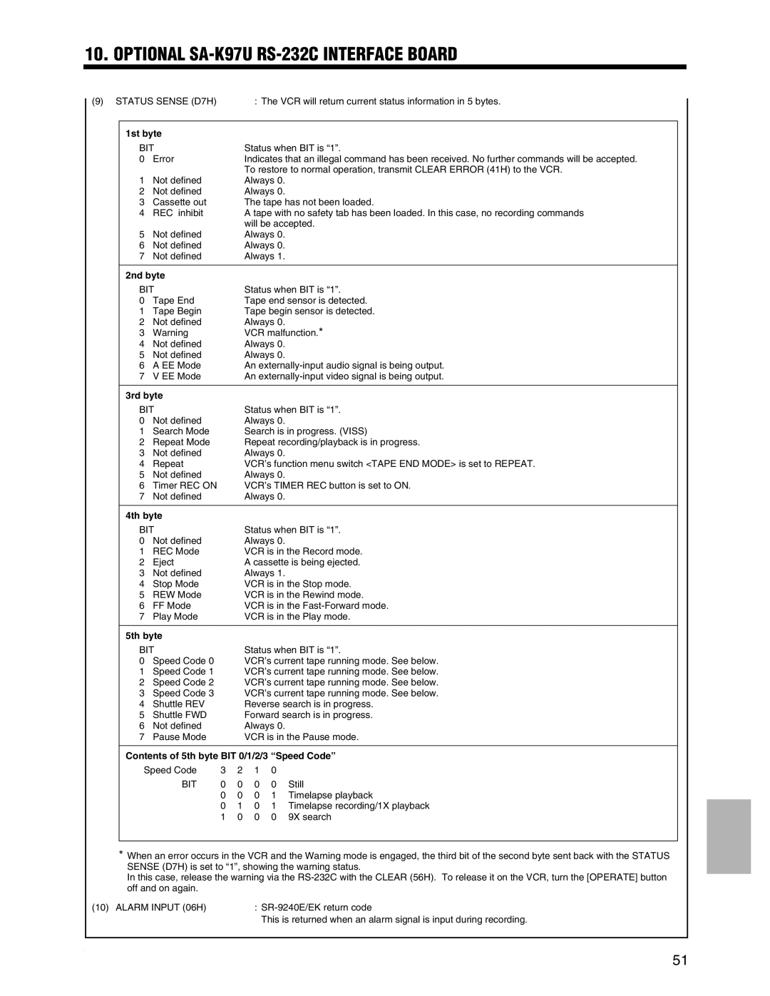
(9) STATUS SENSE (D7H) |
|
| : The VCR will return current status information in 5 bytes. | |||||
|
|
|
|
|
|
|
| |
| 1st byte |
|
|
|
|
|
| |
| BIT |
|
| Status when BIT is “1”. |
| |||
| 0 | Error |
|
| Indicates that an illegal command has been received. No further commands will be accepted. |
| ||
|
|
|
|
| To restore to normal operation, transmit CLEAR ERROR (41H) to the VCR. |
| ||
| 1 | Not defined |
|
| Always 0. |
|
| |
| 2 | Not defined |
|
| Always 0. |
|
| |
| 3 | Cassette out |
|
| The tape has not been loaded. |
| ||
| 4 | REC inhibit |
|
| A tape with no safety tab has been loaded. In this case, no recording commands |
| ||
|
|
|
|
| will be accepted. |
| ||
| 5 | Not defined |
|
| Always 0. |
|
| |
| 6 | Not defined |
|
| Always 0. |
|
| |
| 7 | Not defined |
|
| Always 1. |
|
| |
|
|
|
|
|
|
|
| |
| 2nd byte |
|
|
|
|
|
| |
| BIT |
|
| Status when BIT is “1”. |
| |||
| 0 | Tape End |
|
| Tape end sensor is detected. |
| ||
| 1 | Tape Begin |
|
| Tape begin sensor is detected. |
| ||
| 2 | Not defined |
|
| Always 0. |
|
| |
| 3 | Warning |
|
| VCR malfunction.* |
| ||
| 4 | Not defined |
|
| Always 0. |
|
| |
| 5 | Not defined |
|
| Always 0. |
|
| |
| 6 | A EE Mode |
|
| An |
| ||
| 7 | V EE Mode |
|
| An |
| ||
|
|
|
|
|
|
|
| |
| 3rd byte |
|
|
|
|
|
| |
| BIT |
|
| Status when BIT is “1”. |
| |||
| 0 | Not defined |
|
| Always 0. |
|
| |
| 1 | Search Mode |
|
| Search is in progress. (VISS) |
| ||
| 2 | Repeat Mode |
|
| Repeat recording/playback is in progress. |
| ||
| 3 | Not defined |
|
| Always 0. |
|
| |
| 4 | Repeat |
|
| VCR’s function menu switch <TAPE END MODE> is set to REPEAT. |
| ||
| 5 | Not defined |
|
| Always 0. |
|
| |
| 6 | Timer REC ON |
|
| VCR’s TIMER REC button is set to ON. |
| ||
| 7 | Not defined |
|
| Always 0. |
|
| |
|
|
|
|
|
|
|
| |
| 4th byte |
|
|
|
|
|
| |
| BIT |
|
| Status when BIT is “1”. |
| |||
| 0 | Not defined |
|
| Always 0. |
|
| |
| 1 | REC Mode |
|
| VCR is in the Record mode. |
| ||
| 2 | Eject |
|
| A cassette is being ejected. |
| ||
| 3 | Not defined |
|
| Always 1. |
|
| |
| 4 | Stop Mode |
|
| VCR is in the Stop mode. |
| ||
| 5 | REW Mode |
|
| VCR is in the Rewind mode. |
| ||
| 6 | FF Mode |
|
| VCR is in the |
| ||
| 7 | Play Mode |
|
| VCR is in the Play mode. |
| ||
|
|
|
|
|
|
|
| |
| 5th byte |
|
|
|
|
|
| |
| BIT |
|
| Status when BIT is “1”. |
| |||
| 0 | Speed Code 0 |
|
| VCR’s current tape running mode. See below. |
| ||
| 1 | Speed Code 1 |
|
| VCR’s current tape running mode. See below. |
| ||
| 2 | Speed Code 2 |
|
| VCR’s current tape running mode. See below. |
| ||
| 3 | Speed Code 3 |
|
| VCR’s current tape running mode. See below. |
| ||
| 4 | Shuttle REV |
|
| Reverse search is in progress. |
| ||
| 5 | Shuttle FWD |
|
| Forward search is in progress. |
| ||
| 6 | Not defined |
|
| Always 0. |
|
| |
| 7 | Pause Mode |
|
| VCR is in the Pause mode. |
| ||
|
|
| ||||||
| Contents of 5th byte BIT 0/1/2/3 “Speed Code” |
| ||||||
| Speed Code | 3 | 2 | 1 | 0 |
|
| |
|
| BIT | 0 | 0 | 0 | 0 | Still |
|
|
|
| 0 | 0 | 0 | 1 | Timelapse playback |
|
|
|
| 0 | 1 | 0 | 1 | Timelapse recording/1X playback |
|
|
|
| 1 | 0 | 0 | 0 | 9X search |
|
|
|
|
|
|
|
|
|
|
*When an error occurs in the VCR and the Warning mode is engaged, the third bit of the second byte sent back with the STATUS SENSE (D7H) is set to “1”, showing the warning status.
In this case, release the warning via the
(10) ALARM INPUT (06H) | : |
| This is returned when an alarm signal is input during recording. |
51