3 CONNECTIONS
3-1 Connecting to a Camera
![]() CCD
CCD
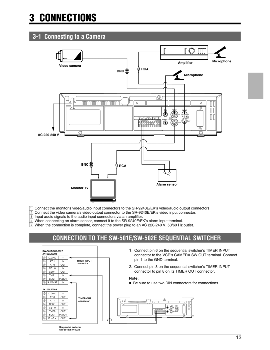
Video camera
AmplifierMicrophone
BNC | RCA |
|
Microphone
|
|
|
|
|
|
| MIC | VIDEO | AUDIO |
|
|
|
|
|
|
| IN |
| |
|
|
|
|
|
|
|
|
| |
|
|
|
|
|
|
|
| IN | IN |
CAM SW | ALARM | ALARM | COM |
| SERIES/CLOCK |
|
|
| |
OUT | IN | REC OUT | WARNING |
|
|
| |||
COM | ALARM | TAPE |
| /REC |
| REMOTE |
|
| |
| RESET | END OUT | OUT | IN OUT |
|
|
| ||
OUT
OUT
AC
BNC | RCA |
|
Alarm sensor
Monitor TV
21Connect the monitor’s video/audio input connectors to the
3Connect the video camera’s video output connector to the
4Input audio signals to the audio input connectors via an amplifier.
5When connecting an alarm sensor, connect it to the
CONNECTION TO THE SW-501E/SW-502E SEQUENTIAL SWITCHER
1. Connect pin 6 on the sequential switcher's TIMER INPUT |
connector to the VCR's CAMERA SW OUT terminal. Connect |
| D.GND |
| – | |||
|
| AT 1 |
| IN | ||
|
| AT 0 |
| OUT | ||
| CS1 0 |
| IN | |||
| CS0 1 |
| OUT | |||
|
|
|
|
| IN | |
|
| TMP1 |
|
| ||
| SODT |
| IN/OUT | |||
|
|
|
| IN | ||
| SLV/MST |
| ||||
|
|
|
|
|
|
|
JK103/JK203 |
|
| ||||
|
|
|
|
|
|
|
| D.GND |
| – | |||
|
| AT 0 |
| OUT | ||
|
| AT 1 |
| IN | ||
| CS0 1 |
| OUT | |||
| CS1 0 |
| IN | |||
|
|
|
|
| OUT | |
|
| TMP0 |
|
| ||
| SODT |
| IN/OUT | |||
| D. +5 V |
| OUT | |||
|
|
|
|
|
|
|
TIMER INPUT connector
TIMER OUT connector
pin 1 to the GND terminal. |
2. Connect pin 8 on the sequential switcher's TIMER INPUT |
connector to pin 8 on its TIMER OUT connector. |
Note:
●Be sure to use two DIN connectors for connections.
MIC | VIDEO | AUDIO |
IN |
| |
| IN | IN |
REMOTE |
| OUT |
|
| |
| OUT |
|
Sequential switcher
13