3 CONNECTIONS
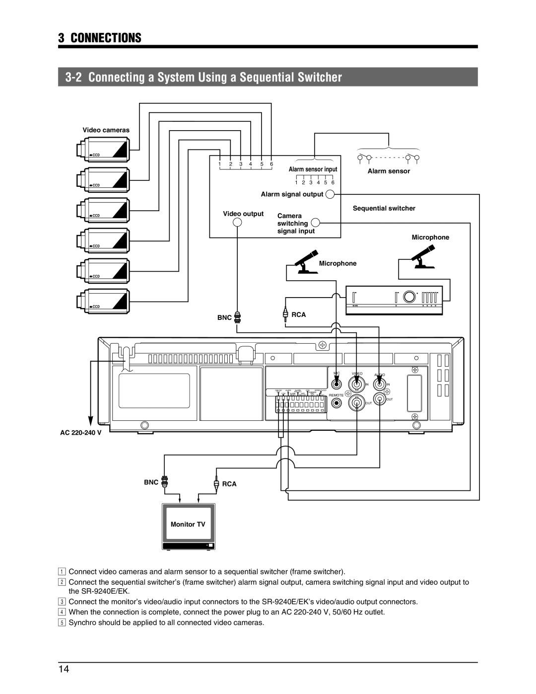
3-2 Connecting a System Using a Sequential Switcher
Video cameras
![]() CCD
CCD
![]() CCD
CCD
![]() CCD
CCD
![]() CCD
CCD
![]() CCD
CCD
![]() CCD
CCD
AC
BNC 
123456 |
| Alarm sensor input |
|
| ||||||
|
| Alarm sensor | ||||||||
|
|
| 123456 |
|
| |||||
Alarm signal output |
|
|
| |||||||
Video output | Camera |
|
|
|
| Sequential switcher | ||||
|
|
|
|
|
| |||||
|
|
|
|
|
|
| ||||
| switching |
|
|
|
|
| ||||
| signal input |
|
|
| Microphone | |||||
|
|
|
|
|
|
|
|
|
| |
|
|
|
|
|
|
| Microphone |
| ||
BNC |
|
| RCA |
|
|
|
|
| ||
|
|
|
|
|
|
|
|
|
| |
|
|
|
|
|
|
|
| MIC | VIDEO | AUDIO |
|
|
|
|
|
|
|
| IN |
| |
|
|
|
|
|
|
|
|
|
| |
|
|
|
|
|
|
|
|
| IN | IN |
| CAM SW | ALARM | ALARM | COM | SERIES/CLOCK |
|
|
| ||
| OUT | IN | REC OUT | WARNING |
|
|
|
| ||
| COM | ALARM | TAPE |
| /REC |
| REMOTE |
|
| |
|
| RESET | END OUT | OUT | IN OUT |
|
| |||
|
|
|
|
|
|
|
|
|
| OUT |
|
|
|
|
|
|
|
|
| OUT |
|
RCA |
|
|
|
|
|
|
|
|
|
|
Monitor TV
21Connect video cameras and alarm sensor to a sequential switcher (frame switcher).
Connect the sequential switcher’s (frame switcher) alarm signal output, camera switching signal input and video output to
3the
4Connect the monitor’s video/audio input connectors to the
5When the connection is complete, connect the power plug to an AC
14