Parts Identification
Become familiar with the buttons and controls on the unit before use. Refer to the pages in parentheses for details.
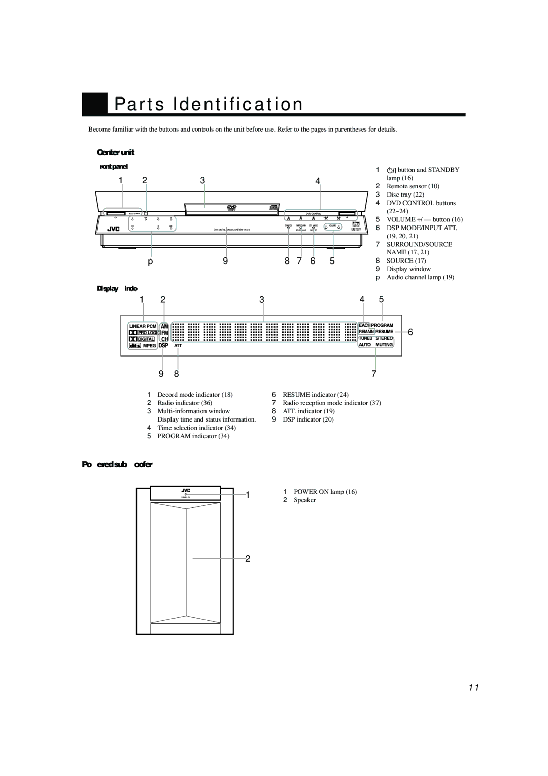
Center unit ———————————————————————————————————————
Front panel |
|
|
|
1 | 2 | 3 | 4 |
p | 9 | 8 7 6 5 |
Display window
1![]()
![]() button and STANDBY lamp (16)
button and STANDBY lamp (16)
2Remote sensor (10)
3 Disc tray (22)
4 DVD CONTROL buttons (22~24)
5 VOLUME +/ – button (16)
6 DSP MODE/INPUT ATT. (19, 20, 21)
7 SURROUND/SOURCE NAME (17, 21)
8 SOURCE (17)
9 Display window
p Audio channel lamp (19)
1 | 2 | 3 | 4 | 5 |
6 |
| 9 8 |
| 7 |
1 | Decord mode indicator (18) | 6 | RESUME indicator (24) |
2 | Radio indicator (36) | 7 | Radio reception mode indicator (37) |
3 | 8 | ATT. indicator (19) | |
| Display time and status information. | 9 | DSP indicator (20) |
4Time selection indicator (34)
5 PROGRAM indicator (34)
Powered sub woofer —————————————————————————————————————
1 | 1 | POWER ON lamp (16) | |
2 | Speaker | ||
| |||
2 |
|
|
11