APPENDIX ●
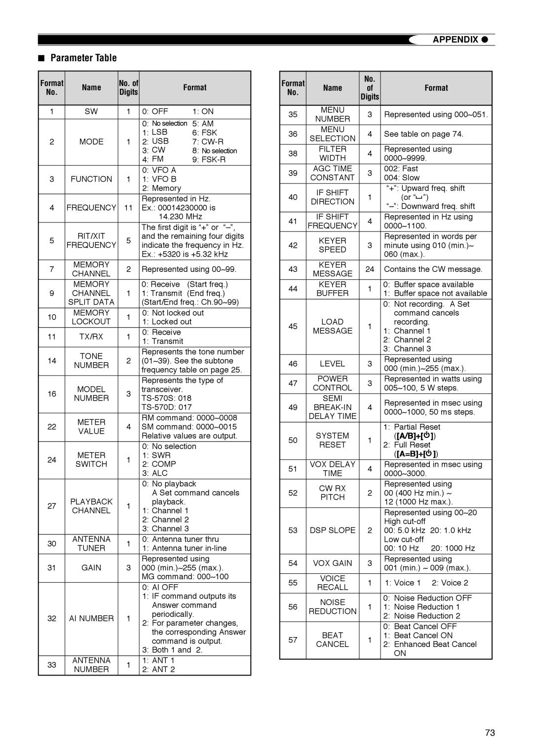
■Parameter Table
Format | Name | No. of |
| Format | ||
No. | Digits |
| ||||
|
|
|
| |||
|
|
|
|
|
| |
1 | SW | 1 | 0: OFF |
| 1: ON | |
|
|
|
|
| ||
|
|
| 0: No selection | 5: AM | ||
|
|
| 1: LSB |
| 6: FSK | |
2 | MODE | 1 | 2: USB |
| 7: | |
|
|
| 3: CW |
| 8: No selection | |
|
|
| 4: FM |
| 9: | |
|
|
| 0: VFO A |
|
| |
3 | FUNCTION | 1 | 1: VFO B |
|
| |
|
|
| 2: Memory |
|
| |
|
|
|
| |||
|
|
| Represented in Hz. | |||
4 | FREQUENCY | 11 | Ex.: 00014230000 is | |||
|
|
| 14.230 MHz | |||
|
|
| The first digit is “+” or | |||
5 | RIT/XIT | 5 | and the remaining four digits | |||
FREQUENCY | indicate the frequency in Hz. | |||||
|
| |||||
|
|
| Ex.: +5320 is +5.32 kHz | |||
|
|
|
|
|
| |
7 | MEMORY | 2 | Represented using 00~99. | |||
CHANNEL | ||||||
|
|
|
|
| ||
| MEMORY |
| 0: Receive | (Start freq.) | ||
9 | CHANNEL | 1 | 1: Transmit | (End freq.) | ||
| SPLIT DATA |
| (Start/End freq.: Ch.90~99) | |||
|
|
|
| |||
10 | MEMORY | 1 | 0: Not locked out | |||
LOCKOUT | 1: Locked out |
| ||||
|
|
| ||||
|
|
|
|
|
| |
11 | TX/RX | 1 | 0: Receive |
|
| |
1: Transmit |
|
| ||||
|
|
|
|
| ||
|
|
|
| |||
| TONE |
| Represents the tone number | |||
14 | 2 | (01~39). See the subtone | ||||
NUMBER | ||||||
|
| frequency table on page 25. | ||||
|
|
| ||||
|
|
| Represents the type of | |||
16 | MODEL | 3 | transceiver. |
|
| |
NUMBER |
| |||||
|
|
| ||||
|
|
|
| |||
|
|
|
| |||
| METER |
| RM command: 0000~0008 | |||
22 | 4 | SM command: 0000~0015 | ||||
VALUE | ||||||
|
| Relative values are output. | ||||
|
|
| ||||
|
|
| 0: No selection | |||
24 | METER | 1 | 1: SWR |
|
| |
SWITCH | 2: COMP |
|
| |||
|
|
|
| |||
|
|
| 3: ALC |
|
| |
|
|
| 0: No playback | |||
|
|
| A Set command cancels | |||
27 | PLAYBACK | 1 | playback. |
| ||
CHANNEL | 1: Channel 1 |
| ||||
|
|
| ||||
|
|
| 2: Channel 2 |
| ||
|
|
| 3: Channel 3 |
| ||
|
|
|
| |||
30 | ANTENNA | 1 | 0: Antenna tuner thru | |||
TUNER | 1: Antenna tuner | |||||
|
| |||||
|
|
|
| |||
|
|
| Represented using | |||
31 | GAIN | 3 | 000 (min.)~255 (max.). | |||
|
|
| MG command: 000~100 | |||
|
|
| 0: AI OFF |
|
| |
|
|
| 1: IF command outputs its | |||
|
|
| Answer command | |||
32 | AI NUMBER | 1 | periodically. | |||
2: For parameter changes, | ||||||
|
|
| ||||
|
|
| the corresponding Answer | |||
|
|
| command is output. | |||
|
|
| 3: Both 1 and | 2. | ||
33 | ANTENNA | 1 | 1: ANT 1 |
|
| |
NUMBER | 2: ANT 2 |
|
| |||
|
|
|
| |||
Format |
| No. |
|
|
|
|
|
|
|
| |
Name | of |
|
| Format | |||||||
No. |
|
| |||||||||
| Digits |
|
|
|
|
|
|
|
| ||
|
|
|
|
|
|
|
|
|
| ||
|
|
|
|
|
|
|
|
|
|
| |
35 | MENU | 3 | Represented using 000~051. | ||||||||
NUMBER | |||||||||||
|
|
|
|
|
|
|
|
|
| ||
|
|
|
|
|
|
|
|
|
|
| |
36 | MENU | 4 | See table on page 74. | ||||||||
SELECTION | |||||||||||
|
|
|
|
|
|
|
|
|
| ||
38 | FILTER | 4 | Represented using | ||||||||
WIDTH | 0000~9999. |
|
|
|
| ||||||
|
|
|
|
|
| ||||||
39 | AGC TIME | 3 | 002: Fast |
| |||||||
CONSTANT | 004: Slow |
| |||||||||
|
|
| |||||||||
| IF SHIFT |
| “+”: Upward freq. shift | ||||||||
40 | 1 | (or “ |
| ”) |
| ||||||
DIRECTION |
|
| |||||||||
|
| ||||||||||
|
|
| |||||||||
|
|
|
|
|
|
|
|
|
| ||
41 | IF SHIFT | 4 | Represented in Hz using | ||||||||
FREQUENCY | 0000~1100. |
|
|
|
| ||||||
|
|
|
|
|
| ||||||
|
|
|
|
|
|
|
|
|
| ||
| KEYER |
| Represented in words per | ||||||||
42 | 3 | minute using 010 (min.)~ | |||||||||
SPEED | |||||||||||
|
| 060 (max.). |
| ||||||||
|
|
|
| ||||||||
43 | KEYER | 24 | Contains the CW message. | ||||||||
MESSAGE | |||||||||||
|
|
|
|
|
|
|
|
|
| ||
44 | KEYER | 1 | 0: Buffer space available | ||||||||
BUFFER | 1: Buffer space not available | ||||||||||
|
| ||||||||||
|
|
| 0: Not recording. A Set | ||||||||
|
|
| command cancels | ||||||||
45 | LOAD | 1 | recording. |
| |||||||
MESSAGE | 1: Channel 1 | ||||||||||
|
| ||||||||||
|
|
| 2: Channel 2 | ||||||||
|
|
| 3: Channel 3 | ||||||||
|
|
|
|
|
|
|
|
|
| ||
46 | LEVEL | 3 | Represented using | ||||||||
000 (min.)~255 (max.). | |||||||||||
|
|
| |||||||||
47 | POWER | 3 | Represented in watts using | ||||||||
CONTROL | 005~100, 5 W steps. | ||||||||||
|
| ||||||||||
| SEMI |
| Represented in msec using | ||||||||
49 | 4 | ||||||||||
0000~1000, 50 ms steps. | |||||||||||
| DELAY TIME |
| |||||||||
|
|
|
|
|
|
|
|
|
| ||
|
|
|
|
|
|
|
|
|
| ||
|
|
| 1: Partial Reset | ||||||||
50 | SYSTEM | 1 | ([A/B]+[ |
|
|
|
| ]) | |||
| |||||||||||
RESET | 2: Full Reset |
| |||||||||
|
|
| |||||||||
|
|
| ([A=B]+[ |
| ]) | ||||||
|
|
|
| ||||||||
51 | VOX DELAY | 4 | Represented in msec using | ||||||||
TIME | 0000~3000. |
|
|
|
| ||||||
|
|
|
|
|
| ||||||
| CW RX |
| Represented using | ||||||||
52 | 2 | 00 (400 Hz min.) ~ | |||||||||
PITCH | |||||||||||
|
| 12 (1000 Hz max.). | |||||||||
|
|
| |||||||||
|
|
|
|
|
|
|
|
|
| ||
|
|
| Represented using 00~20 | ||||||||
|
|
| High |
| |||||||
53 | DSP SLOPE | 2 | 00: 5.0 kHz 20: 1.0 kHz | ||||||||
|
|
| Low |
| |||||||
|
|
| 00: 10 Hz | 20: 1000 Hz | |||||||
54 | VOX GAIN | 3 | Represented using | ||||||||
001 (min.) ~ 009 (max.). | |||||||||||
|
|
| |||||||||
55 | VOICE | 1 | 1: Voice 1 | 2: Voice 2 | |||||||
RECALL | |||||||||||
|
|
|
|
|
|
|
|
|
| ||
| NOISE |
| 0: Noise Reduction OFF | ||||||||
56 | 1 | 1: Noise Reduction 1 | |||||||||
REDUCTION | |||||||||||
|
| 2: Noise Reduction 2 | |||||||||
|
|
| |||||||||
|
|
|
|
|
|
|
|
|
| ||
|
|
| 0: Beat Cancel OFF | ||||||||
57 | BEAT | 1 | 1: Beat Cancel ON | ||||||||
CANCEL | 2: Enhanced Beat Cancel | ||||||||||
|
| ||||||||||
|
|
| ON |
| |||||||
73