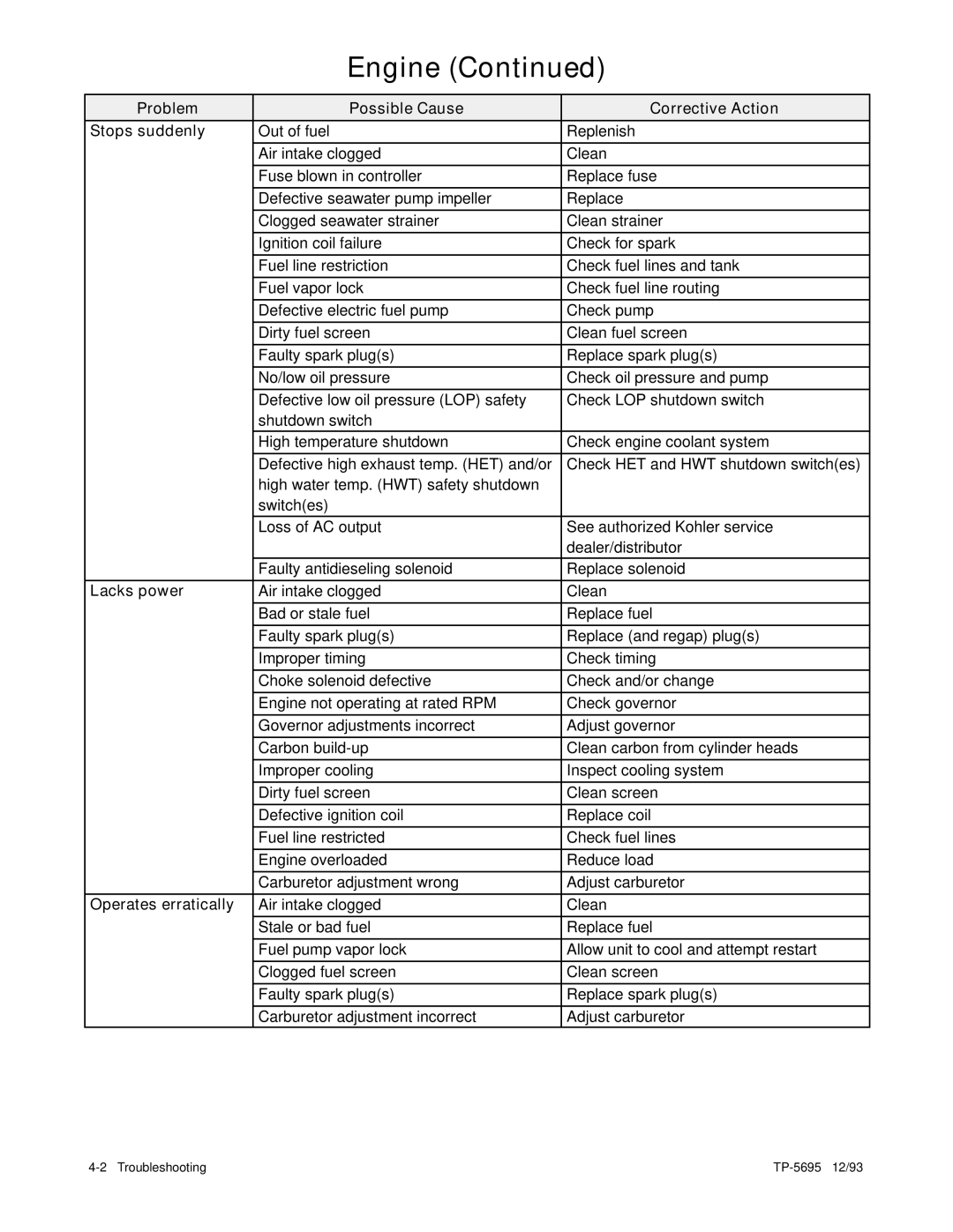
3.5CFZ 4CZ 5CFZ 6.5CZ
Marine Generator Sets
Models
TP-5695 12/93
California Proposition
Section 3. Scheduled Maintenance
Table of Contents
Safety Precautions and Instructions
Section 4. Troubleshooting
DANGER
Safety Precautions and Instructions
HAZARDOUS VOLTAGE ELECTRICAL SHOCK
Moving rotor
Carbon monoxide can cause severe nausea
EXHAUST SYSTEM
Carbon monoxide Can cause severe nausea, fainting, or death
Carbon monoxide can cause severe nausea
BATTERY
Sulfuric acid in batteries Can cause severe injury or death
Sulfuric acid in batteries can cause severe injury or
Gasoline vapors can cause explosion and severe injury or death
FUEL SYSTEM
Explosion
Explosive fuel vapors Can cause severe injury or death
HOT PARTS
ACCIDENTAL STARTING
MOVING PARTS
Accidental starting Can cause severe injury or death
Fire Can cause severe injury or death
ENGINE BACKFIRE/FLASH FIRE
HAZARDOUS NOISE
A sudden backfire can cause severe injury or death
Check zinc anode every 100 hours or 3 months
This generator set has been rewired from its nameplate voltage to
This is a positive terminal only Do not attach negative lead
Do not use as a step
Reference Material
Pleasure Craft
Commercial Vessels
Additional References
Routine Service Parts
Part Description
Kohler Part No
Description
Glossary of Abbreviations
Abbreviation
Abbreviation
Abbreviation
Abbreviation
Description
Description
General Specifications
Section 1. Specifications
Specifications
Introduction
5CFZ/6.5CZ
Generator
3.5CFZ/4CZ
3.5CFZ
5CFZ/6.5CZ
Engine
3.5CFZ/4CZ
2.28 x
Engine Continued
3.5CFZ/4CZ
5CFZ/6.5CZ
12-Inch Remote Wiring Harness
Accessories
Ship-to-Shore Transfer Switch
Sound Shield
Service Views
Figure 1-1. Service Views typical
Section 2. Operation
Prestart Checks
Controller
Figure 2-1. Controller
Explosion
Starting
Stopping
Gasoline vapors can cause explosion and severe injury or death
Low Oil Pressure Shutdown Switch
Engine Safety Shutdown Switches
Battery-Charging Fuse 10 Amp
Figure 2-2. Low Oil Pressure Shutdown Switch
Shutdown Switch
High Water Temperature
High Exhaust Temperature
Shutdown Switches
Remote Panels Optional
Figure 2-5. Remote Panel Features
Figure 2-6. Remote Start and Two-Meter Panel Features
Remote Start Panel
Figure 2-7. Remote Start and Four-Meter Features
Water Temperature
Remote Start and Four-Meter Panel Kit
Section 3. Scheduled Maintenance
Accidental starting Can cause severe injury or death
Accidental starting can cause severe injury or
Every
Service Schedule
After
Before
ELECTRICAL SYSTEM
Service Schedule Continued
REMOTE CONTROL SYSTEM
ENGINE AND MOUNTING
When Outside Temperature
Specifications
Figure 3-1. Oil Service Class and SAE Viscosity Grade Symbol
Lubrication System
Figure 3-4. Adding Oil
Adding Oil
Oil Change/Oil Filter Change
Figure 3-5. Oil Drain Cap
Fuel System
Figure 3-6. Removing Oil Filter
Specifications
Explosive fuel vapors Can cause severe injury or death
Fuel Pump Screen
Figure 3-7. Fuel Pump Screen
Explosive fuel vapors can cause severe injury or
Carburetor/Choke Lubrication
Carburetor Adjustments
Figure 3-8. Fuel Mixture Adjustment
Fire Can cause severe injury or death
Ignition System
Ignition System Service
Figure 3-9. Removing Spark Plug Wires
Spark Plugs
Possible Cause
Problem
Means of Identification
Normal
Scheduled Maintenance
Figure 3-13. Adjusting Spark Plug Gap
Figure 3-12. Checking Spark Plug Gap
0.028--0.031 in
Cooling Systems- Closed/Heat Exchanger
Filling and Checking
Hot coolant and steam Can cause severe injury or death
Figure 3-16. Checking Coolant Level
Figure 3-14. Air-Bleed Screw
Figure 3-15. Coolant Pressure Cap
Coolant Recovery Tank
Accidental starting can cause severe injury or
Flushing and Cleaning
Accidental starting Can cause severe injury or death
Hot coolant and steam Can cause severe injury or death
13. Reconnect battery, negative lead last
Anticorrosion Zinc
Figure 3-17. Removing Anticorrosion Zinc
Figure 3-19. Air Cleaner Service
Air Cleaner and Mixing Elbow
Servicing Air Cleaner
Pressure Cap
Checking Electrolyte Level
Battery
Cleaning
Checking Specific Gravity
Figure 3-21. Specific Gravity Temperature Correction
Charging
Exposed moving parts can cause severe injury or
Valve Adjustment
Rotating parts Can cause severe injury or death
Flying projectiles can cause severe injury or death
Adjusting Screw 3 mm
Figure 3-23. Valve Adjustment
Figure 3-22. Determining Top Dead Center
Scheduled Maintenance
Governor
Governor Adjustment
Figure 3-24. Governor Adjustment
Lubrication
Generator Service
Wattage Requirements
General
Storage Procedure
Corrective Action
Section 4. Troubleshooting
Engine
Unit will not crank
Stops suddenly
Lacks power
Engine Continued
Operates erratically
Overheats
Battery will not
Electrical System
Unit is noisy
Low output or
Generator
No AC output
excessive drop in
Wiring Diagrams
Section 5. Wiring Diagrams
Figure 5-1. Schematic Wiring Diagram--3.5CFZ, 4CZ, 5CFZ, and 6.5CZ
TP-5695 12/93
Wiring
Wiring
Diagram
Diagrams
Early Rectangular Design
Electro Switch
Kraus Naimler/American Solenoid
120- or 110-Volt 3-Wire 2-Pole Configuration--Figure
Four-Lead Reconnectable Single-Phase Generator Sets Where Generator
120- or 110- Volt 2-Wire Configuration Figure 5-5 Single Pole
Figure 5-5. 120 Volt, 2-Wire
Figure 5-6. Without Jumper Lead
120/240- or 110/220-Volt Configuration--Figure
L1--L3
LO Neutral
Page
Motor Loads
Section 6. Installation
Generator Selection and Wattage Requirements
Lighting Load
Kilowatt Derating
“Power to
Appliance Loads
Motor
Figure 6-4. Typical Location and Mounting
INPUT STOP/START 10A FUSE 00000 1/10 TOTAL HOURS BATT CHRG
Mounting
LocationVentilation
Space
Air Requirements CFM L/min
Figure 6-6. Dual Dip Tubes
Fuel Systems
Fuel Supply
Figure 6-7. Single Dip Tube
Fuel Pump Lift Capabilities and Fuel Consumption
Anti-Siphon Provisions
Fuel Lines
Figure 6-8. Fuel Pump Inlet Connection
Figure 6-11. Intake Strainer
Figure 6-12. Seacock Installation
Cooling Systems
General
Closed/Heat Exchanger
Figure 6-13. Seawater Strainer
Figure 6-14. Seawater Inlet Connection
Figure 6-16. Mixer Elbow/Exhaust Connection
Exhaust Systems
Figure 6-15. Closed/Heat Exchanger Cooling System
General
Can cause severe nausea, fainting, or death
Figure 6-17. Typical Above Waterline Installation
Carbon monoxide
Carbon monoxide can cause severe nausea
Mid/Below Waterline
Figure 6-19. Typical Mid and Below Waterline Installation
Above Waterline
Figure 6-18. Siphon Break Components
AC Voltage Connections
Installation in Steel or Aluminum Vessels
Electrical Systems
Explosion
Battery
Battery
Wiring
Figure 6-20. Battery Cable Sizes
Lead Designations
Remote Start Switch Connection
Figure 6-22. Remote Control Panel Wiring
Lead
Installation Drawings
7-1. Dimension Drawing--3.5CFZ, 4CZ, 5CFZ, and 6.5CZ
7. Installation Drawings
Section
Installation Drawings
Sound Shield--Optional on 3.5CFZ and 4CZ
Standard on 5CFZ and 6.5CZ
12/93
Section 8. Parts Ordering Instructions
SERVICE
Section 9. Operating Hour Service Log
SERVICE RECORD
DATE
TP-5695 12/93 PRINTED IN U.S.A
KOHLER CO. KOHLER, WISCONSIN 53044 PHONE