Output Can Be Reconnected For 120 volt or 120/240 volt, 60 Hz,
110 volt or 110/220 volt, 50 Hz
NOTE
When a generator set is reconnected to a voltage different than nameplate voltage, notice should be placed on the unit indicating this change. Decals for this purpose are available from authorized Kohler dealers/distributors.
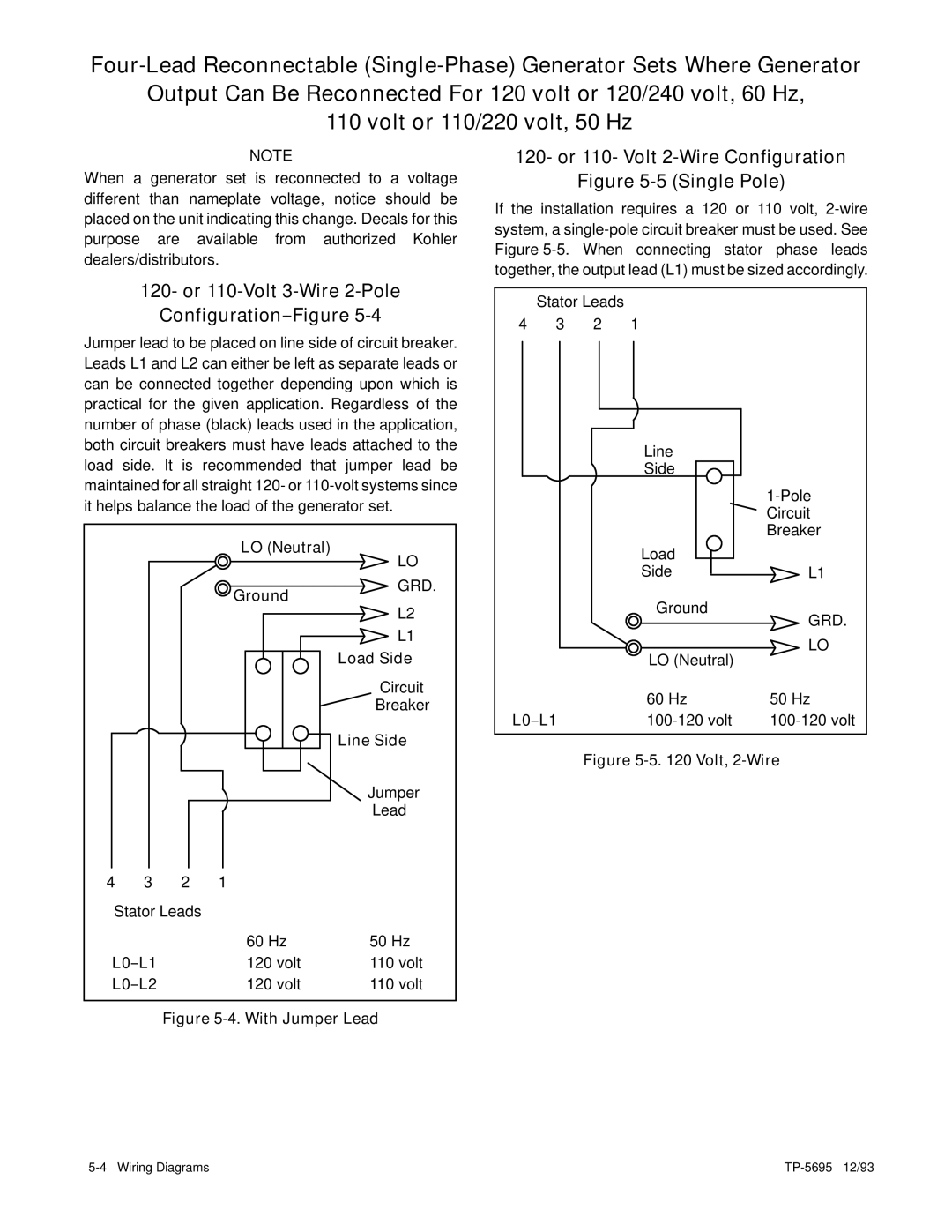
120- or 110- Volt 2-Wire Configuration
Figure 5-5 (Single Pole)
If the installation requires a 120 or 110 volt,
120- or 110-Volt 3-Wire 2-Pole
Configuration--Figure 5-4
Jumper lead to be placed on line side of circuit breaker. Leads L1 and L2 can either be left as separate leads or can be connected together depending upon which is practical for the given application. Regardless of the number of phase (black) leads used in the application, both circuit breakers must have leads attached to the load side. It is recommended that jumper lead be maintained for all straight 120- or
LO (Neutral)
| LO | |
Ground | GRD. | |
L2 | ||
| ||
| L1 | |
| Load Side | |
| Circuit | |
| Breaker | |
| Line Side |
Stator Leads
4 3 2 1
Line
Side
| Load |
| Side |
| Ground |
| LO (Neutral) |
| 60 Hz |
|
L1
GRD.
LO
50 Hz
|
|
|
| Jumper |
|
|
|
| Lead |
4 | 3 | 2 | 1 |
|
Stator Leads |
|
| ||
|
|
| 60 Hz | 50 Hz |
|
| 120 volt | 110 volt | |
|
| 120 volt | 110 volt | |
