Section 4. Troubleshooting
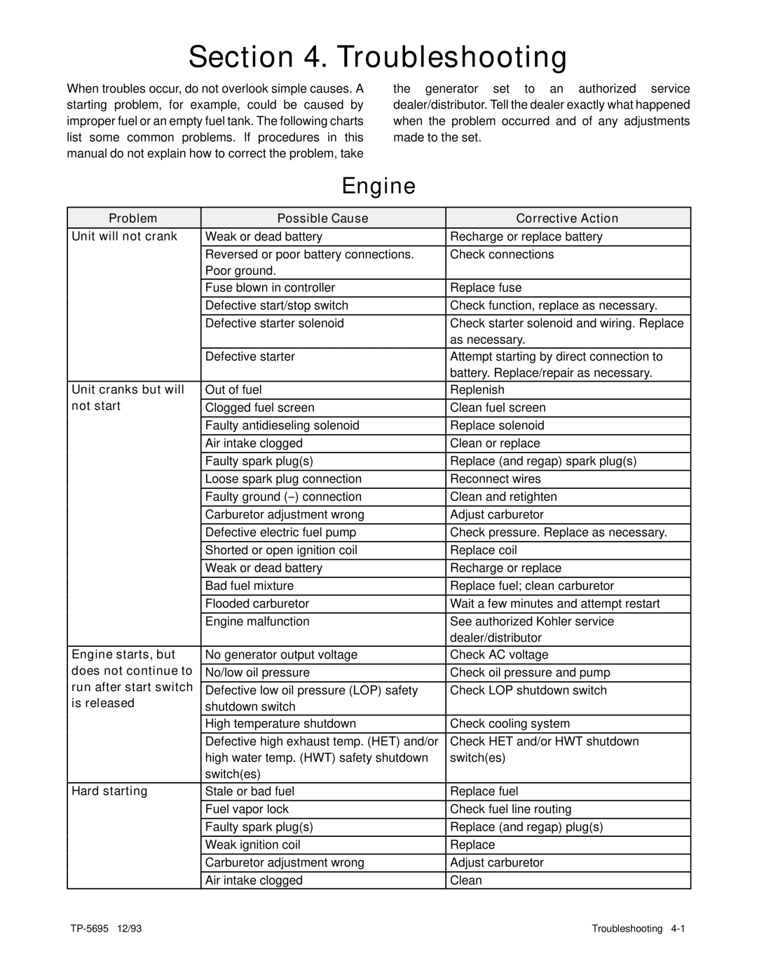
When troubles occur, do not overlook simple causes. A starting problem, for example, could be caused by improper fuel or an empty fuel tank. The following charts list some common problems. If procedures in this manual do not explain how to correct the problem, take
the generator set to an authorized service dealer/distributor. Tell the dealer exactly what happened when the problem occurred and of any adjustments made to the set.
Engine
Problem | Possible Cause | Corrective Action |
Unit will not crank | Weak or dead battery | Recharge or replace battery |
| Reversed or poor battery connections. | Check connections |
| Poor ground. |
|
| Fuse blown in controller | Replace fuse |
| Defective start/stop switch | Check function, replace as necessary. |
| Defective starter solenoid | Check starter solenoid and wiring. Replace |
|
| as necessary. |
Defective starter
Attempt starting by direct connection to battery. Replace/repair as necessary.
Unit cranks but will | Out of fuel | Replenish |
not start | Clogged fuel screen | Clean fuel screen |
| Faulty antidieseling solenoid | Replace solenoid |
| Air intake clogged | Clean or replace |
| Faulty spark plug(s) | Replace (and regap) spark plug(s) |
| Loose spark plug connection | Reconnect wires |
| Faulty ground | Clean and retighten |
| Carburetor adjustment wrong | Adjust carburetor |
| Defective electric fuel pump | Check pressure. Replace as necessary. |
| Shorted or open ignition coil | Replace coil |
| Weak or dead battery | Recharge or replace |
| Bad fuel mixture | Replace fuel; clean carburetor |
| Flooded carburetor | Wait a few minutes and attempt restart |
| Engine malfunction | See authorized Kohler service |
|
| dealer/distributor |
Engine starts, but does not continue to run after start switch is released
No generator output voltage | Check AC voltage |
No/low oil pressure | Check oil pressure and pump |
Defective low oil pressure (LOP) safety | Check LOP shutdown switch |
shutdown switch |
|
High temperature shutdown | Check cooling system |
Defective high exhaust temp. (HET) and/or | Check HET and/or HWT shutdown |
high water temp. (HWT) safety shutdown | switch(es) |
switch(es) |
|
Hard starting
Stale or bad fuel | Replace fuel |
Fuel vapor lock | Check fuel line routing |
Faulty spark plug(s) | Replace (and regap) plug(s) |
Weak ignition coil | Replace |
Carburetor adjustment wrong | Adjust carburetor |
Air intake clogged | Clean |
Troubleshooting |