Above Waterline |
| 1 | ||
In addition to considerations described earlier, a |
| |||
|
| |||
|
| |||
outlet at a maximum of 10 horizontal ft. (3 m) from the |
|
| ||
center of the engine’s exhaust outlet (see Figure |
|
| ||
A typical silencer should be mounted with the inlet and |
| 2 | ||
outlet level and with the drain plug down. The silencer |
| |||
|
| |||
may require two supporting brackets or hanger straps |
| 3 | ||
for installation to stringers or other suitable structure. |
| |||
Any “lift”in the exhaust line to improve silencing must be |
|
| ||
below the engine exhaust manifold outlet. |
|
| ||
Mid/Below Waterline |
|
| ||
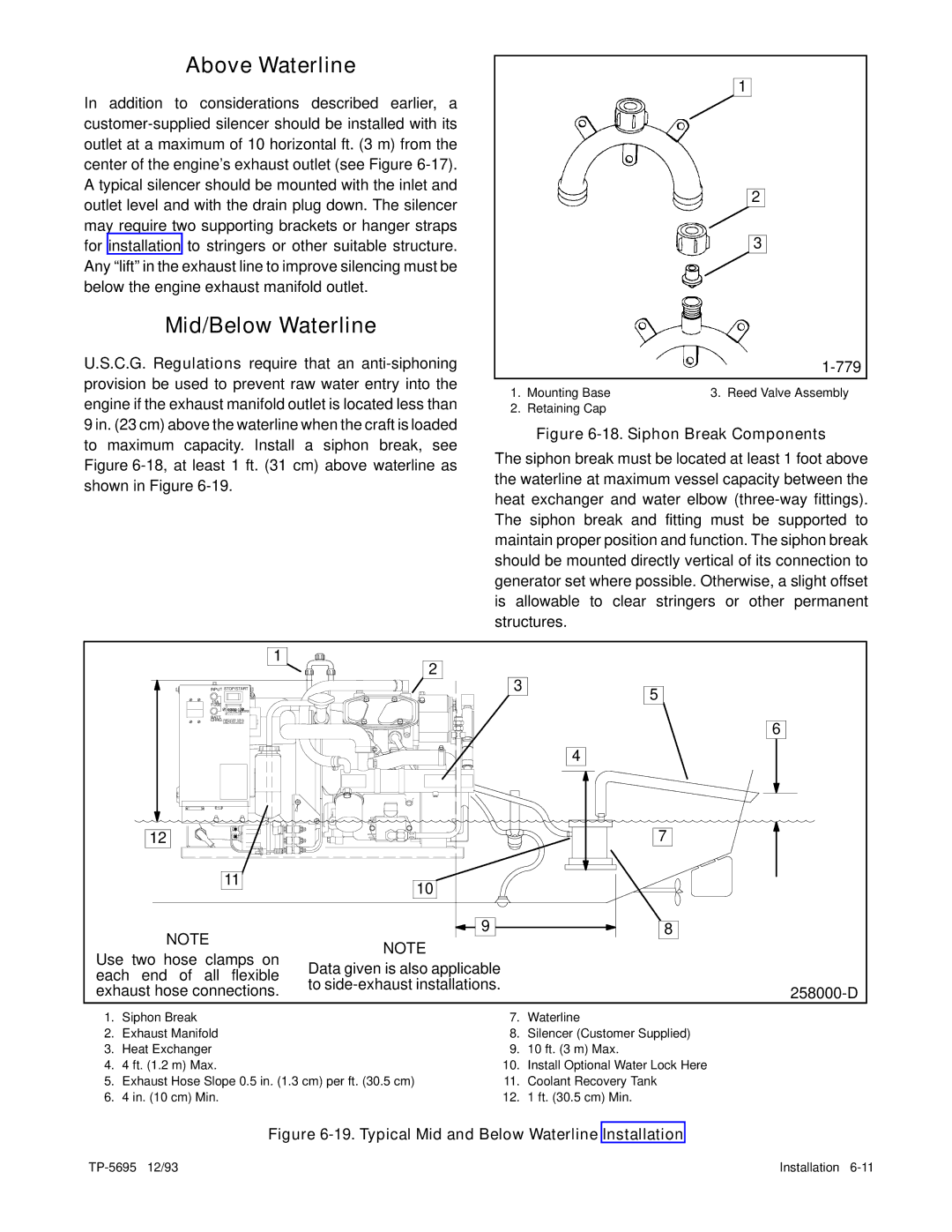
U.S.C.G. Regulations require that an |
| |||
provision be used to prevent raw water entry into the | 1. Mounting Base | 3. Reed Valve Assembly | ||
engine if the exhaust manifold outlet is located less than | ||||
2. Retaining Cap |
| |||
9 in. (23 cm) above the waterline when the craft is loaded | Figure | |||
to maximum capacity. Install a siphon break, see | ||||
The siphon break must be located at least 1 foot above | ||||
Figure | ||||
the waterline at maximum vessel capacity between the | ||||
shown in Figure |
| |||
| heat exchanger and water elbow | |||
|
| |||
|
| The siphon break and fitting must be supported to | ||
|
| maintain proper position and function. The siphon break | ||
|
| should be mounted directly vertical of its connection to | ||
|
| generator set where possible. Otherwise, a slight offset | ||
|
| is allowable to clear stringers or other permanent | ||
|
| structures. |
| |
| 1 |
|
| |
| 2 | 3 |
| |
INPUT STOP/START | 5 | |||
10A |
|
| ||
FUSE | 1/10 |
|
| |
00000 |
|
| ||
TOTAL HOURS |
|
| ||
BATT. |
|
| 6 | |
CHRG. |
|
| ||
|
|
| ||
|
| 4 |
| |
| 12 |
|
| 7 |
| 11 | 10 |
|
|
|
|
|
| |
| NOTE | 9 |
| 8 |
| NOTE |
|
| |
Use two hose clamps on |
|
| ||
Data given is also applicable |
|
| ||
each end of all flexible |
|
| ||
to |
|
| ||
exhaust hose connections. |
|
| ||
|
| |||
1. | Siphon Break |
| 7. | Waterline |
2. | Exhaust Manifold |
| 8. | Silencer (Customer Supplied) |
3. | Heat Exchanger |
| 9. | 10 ft. (3 m) Max. |
4. | 4 ft. (1.2 m) Max. |
| 10. | Install Optional Water Lock Here |
5. | Exhaust Hose Slope 0.5 in. (1.3 cm) per ft. (30.5 cm) | 11. | Coolant Recovery Tank | |
6. | 4 in. (10 cm) Min. |
| 12. | 1 ft. (30.5 cm) Min. |
Figure 6-19. Typical Mid and Below Waterline Installation
Installation |