Locate the exhaust outlet at least 4 in. (10 cm) above the | Carbon monoxide can cause severe nausea, | |||||
waterline when the craft is loaded to maximum capacity. | fainting, or death. Use the following precautions when | |||||
Usually a flapper is installed at exhaust (transom) outlet | installing and operating generator set. Carbon | |||||
to prevent water backup in following seas or when going | monoxide is particularly threatening in that it is an | |||||
astern (backward). |
|
| odorless, colorless, tasteless, nonirritating gas. Be | |||
| WARNING |
| especially careful if operating the generator when | |||
|
| moored or anchored under calm conditions as gases | ||||
|
|
|
| |||
|
|
|
| may accumulate. If operating the set dockside, moor | ||
|
|
|
| your craft so that the exhaust discharges on the lee side | ||
|
|
|
| (the side sheltered from the wind), and always be | ||
|
|
|
| mindful of others— make sure your exhaust is directed | ||
|
|
|
| away from other boats and occupied buildings. Do not | ||
Carbon monoxide. |
|
| install exhaust outlet where exhaust can be drawn | |||
Can cause severe nausea, fainting, or death. | through portholes, vents, or air conditioners. If | |||||
The exhaust system must be | leakproof | and | generator set’s exhaust discharge hole is near to your | |||
craft’s waterline, DO NOT OVERLOAD CRAFT so as to | ||||||
routinely inspected. |
|
| ||||
|
| close or restrict exhaust discharge hole. | ||||
|
|
|
| |||
NOTE |
|
|
|
| ||
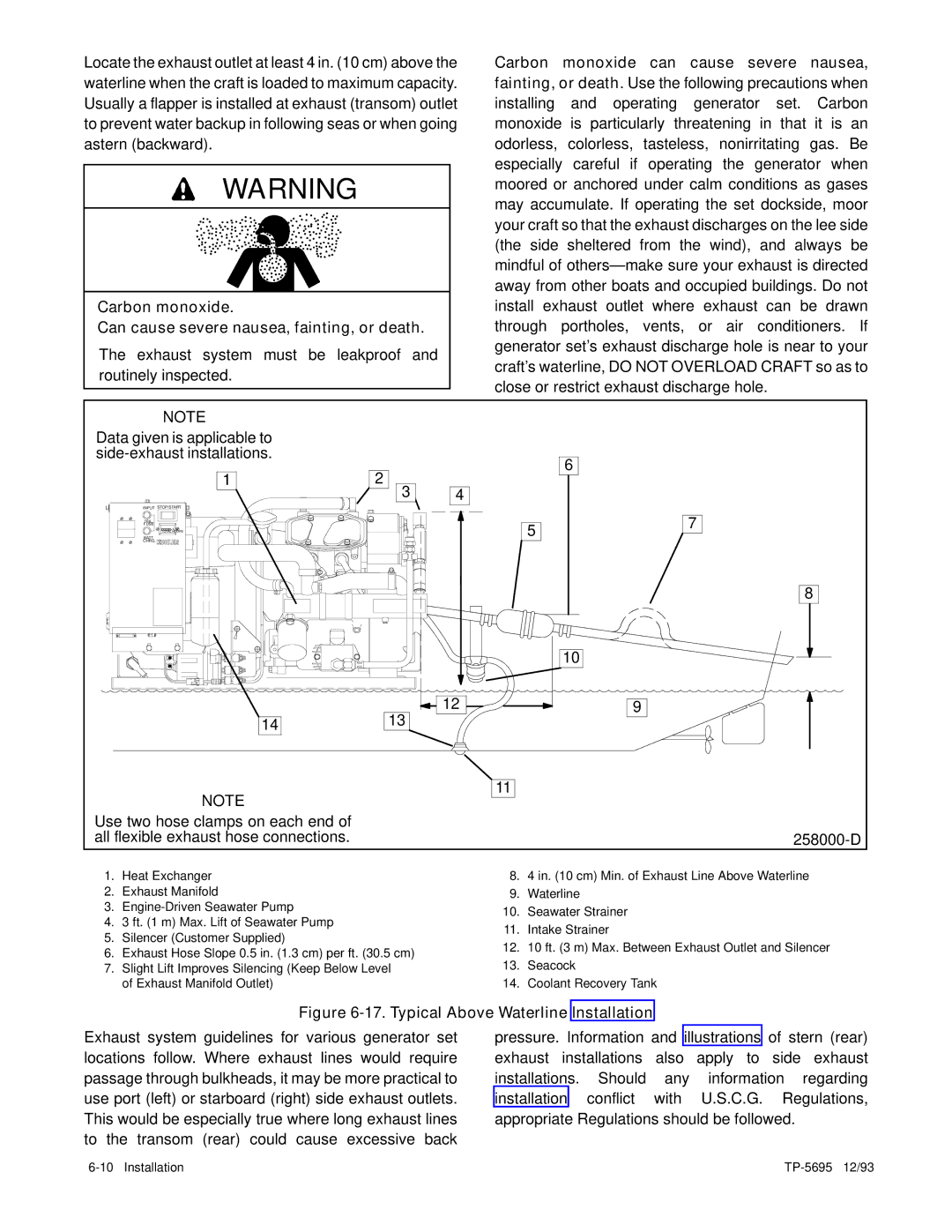
Data given is applicable to |
|
|
|
| ||
|
|
| 6 | |||
| 1 | 2 |
|
| ||
| 4 |
|
| |||
|
| 3 |
|
| ||
INPUT STOP/START |
|
|
|
| ||
10A |
|
|
| 5 | 7 | |
FUSE |
|
|
| |||
000 00 | 1/10 |
|
| |||
TOTAL HOURS |
|
| ||||
BATT. |
|
|
|
| ||
CHRG. |
|
|
|
|
| |
|
|
|
|
| 8 | |
|
|
|
|
| 10 | |
| 14 | 13 | 12 |
| 9 | |
|
|
|
| |||
NOTE
11
Use two hose clamps on each end of |
|
all flexible exhaust hose connections. |
1.Heat Exchanger
2.Exhaust Manifold
3.
4.3 ft. (1 m) Max. Lift of Seawater Pump
5.Silencer (Customer Supplied)
6.Exhaust Hose Slope 0.5 in. (1.3 cm) per ft. (30.5 cm)
7.Slight Lift Improves Silencing (Keep Below Level of Exhaust Manifold Outlet)
8.4 in. (10 cm) Min. of Exhaust Line Above Waterline
9.Waterline
10.Seawater Strainer
11.Intake Strainer
12.10 ft. (3 m) Max. Between Exhaust Outlet and Silencer
13.Seacock
14.Coolant Recovery Tank
Figure 6-17. Typical Above Waterline Installation
Exhaust system guidelines for various generator set locations follow. Where exhaust lines would require passage through bulkheads, it may be more practical to use port (left) or starboard (right) side exhaust outlets. This would be especially true where long exhaust lines to the transom (rear) could cause excessive back
pressure. Information and illustrations of stern (rear) exhaust installations also apply to side exhaust installations. Should any information regarding installation conflict with U.S.C.G. Regulations, appropriate Regulations should be followed.