INPUT STOP/START
10A FUSE
00 0 0 0 1/10
TOTAL HOURS
BATT.
CHRG.
11
1
2
10
3
4
5
6
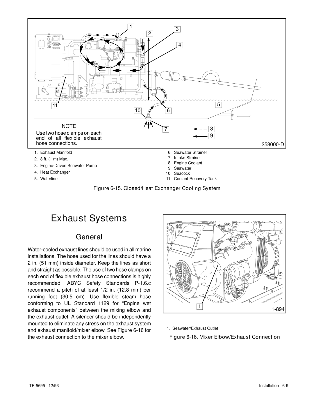
NOTE
Use two hose clamps on each end of all flexible exhaust hose connections.
7
![]()
![]()
![]()
![]() 8
8
![]()
![]() 9
9
1. | Exhaust Manifold | 6. | Seawater Strainer | |
2. | 3 ft. (1 m) Max. | 7. | Intake Strainer | |
3. | 8. | Engine Coolant | ||
9. | Seawater | |||
4. | Heat Exchanger | |||
10. | Seacock | |||
5. | Waterline | 11. | Coolant Recovery Tank |
Figure 6-15. Closed/Heat Exchanger Cooling System
Exhaust Systems
General
1 | |
| |
1. Seawater/Exhaust Outlet |
|
Figure 6-16. Mixer Elbow/Exhaust Connection
Installation |