Manuals
/
Kramer Electronics
/
TV and Video
/
Universal Remote
Kramer Electronics
RC-SV
manual
Driver Manager Window
Models:
RC-SV
1
13
42
42
Download
42 pages
42.22 Kb
10
11
12
13
14
15
16
17
Install
Connecting via the Ethernet
RC-SV Configuration Guide
Creating an IR Command
Driver Manager Window Features
Page 13
Image 13
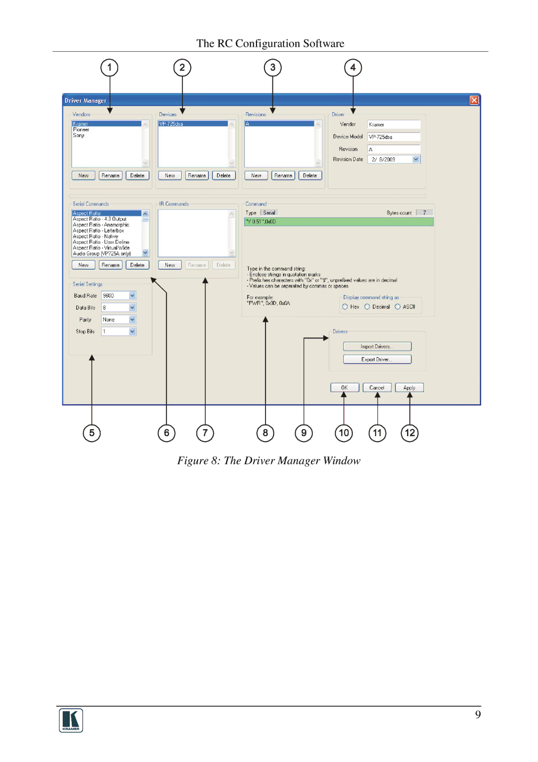
The RC Configuration Software
Figure 8: The Driver Manager Window
9
Page 12
Page 14
Page 13
Image 13
Page 12
Page 14
Contents
RC-SV Configuration Guide
Contents
Figures
Tables
Overview
Introduction
Microsoft Windows XP is the recommended operating system3
Media Room Components List
Initial Planning
Installing the Software
RC Configuration Software
Install the Kramer RC Configuration 2 application
Change Working Directory Window
Downloading and Installing the Drivers
Open the Kramer RC Configuration 2 program
Define the Driver Manager window
Driver Manager Window
Feature Function
Driver Manager Window Features
Serial Command type area appears, as illustrated in Figure
Creating an IR Command
Port Mapping
IR Command Area Window
Sony DVD Player in the RC Command Area
Port Manager Window Features
Kramer RC Configuration Main Window
Device Area
Kramer RC Configuration Window Features
Shows the Event Macros Tab
Shows the Toggle button behavior
Switcher Port RC Command Area
Creating a Macro
Ignore Button Port RC Command Area
Creating a New Command
Labeling the Buttons
Setting the Delay Time and Button Lighting
Switch to COMP1 Command
Creating a Driver Command
Relay Command Turn Lights on
Power Amplifier Command
An LCD Keypad Command
Ignore Button Command
File Menu Features
Kramer RC Configuration Menus
File Menu
Edit Menu Features
Configuration Menu
Configuration Menu Features
Edit Menu
Device Menu
Device Menu Features
Connect Dialog Box
Help Menu
Help Menu Features
Load Firmware
Load Firmware Upgrade Window SV-551
Load Firmware Upgrade Window RC-6x
Transforming to the Stand Alone Configuration
Connecting a Room Controller as a Stand Alone Device Master
Device Properties Window in the Stand Alone Mode
Port Manager in the Stand Alone Mode
Local Area Connection Properties Window
Connecting via the Ethernet
Internet Protocol TCP/IP Properties Window
Writing a Configuration
Loading a Configuration
Top
Page
Image
Contents