The RC Configuration Software
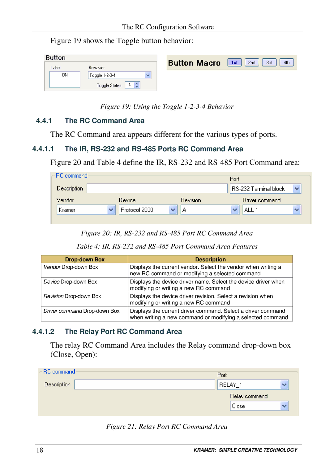
Figure 19 shows the Toggle button behavior:
Figure 19: Using the Toggle 1-2-3-4 Behavior
4.4.1The RC Command Area
The RC Command area appears different for the various types of ports.
4.4.1.1The IR, RS-232 and RS-485 Ports RC Command Area
Figure 20 and Table 4 define the IR, RS-232 and RS-485 Port Command area:
Figure 20: IR, RS-232 and RS-485 Port RC Command Area
Table 4: IR, RS-232 and RS-485 Port Command Area Features
| Description |
Vendor | Displays the current vendor. Select the vendor when writing a |
| new RC command or modifying a selected command |
Device | Displays the device driver name. Select the device driver when |
| modifying or writing a new RC command |
Revision | Displays the device driver revision. Select a revision when |
| modifying or writing a new RC command |
Driver command | Displays the current driver command. Select a driver command |
| when writing a new command or modifying a selected command |
4.4.1.2The Relay Port RC Command Area
The relay RC Command Area includes the Relay command
Figure 21: Relay Port RC Command Area
18 | KRAMER: SIMPLE CREATIVE TECHNOLOGY |