Manuals
/
Kramer Electronics
/
Computer Equipment
/
Projector
Kramer Electronics
VP-725XLA user manual Installing in a Rack, Kramer Simple Creative Technology
Models:
VP-725XLA
1
16
67
67
Download
67 pages
1.9 Kb
13
14
15
16
17
18
19
20
<
>
Specs
Install
Error codes
Warranty
Configuring and Controlling the VP-725XLA
Connecting the VP-725XLA Presentation Switcher / Scaler
The Setup Screen
Note For set function command, parameter will
Adjusting the Audio Level
defines the settings available for each application
Page 16
Image 16
Installing in a Rack
5 Installing in a Rack
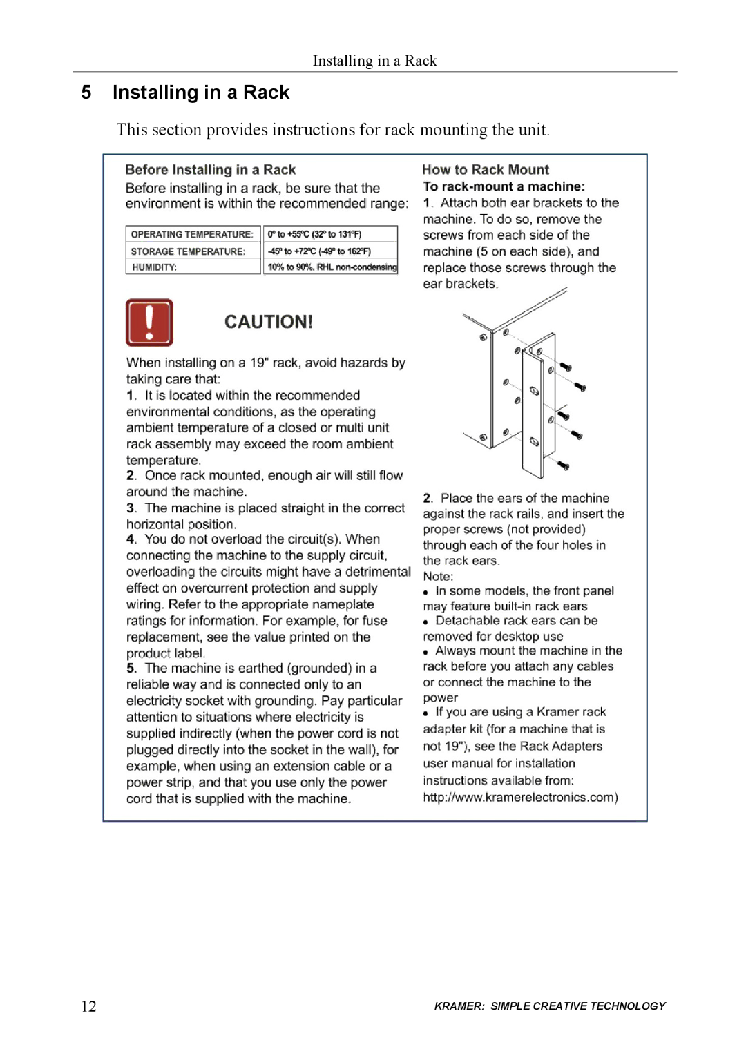
This section provides instructions for rack mounting the unit.
12
KRAMER: SIMPLE CREATIVE TECHNOLOGY
Page 15
Page 17
Page 16
Image 16
Page 15
Page 17
Contents
NeVc
Contents
Your VP-725XLA Presentation Switcher / Scaler
Installing in a Rack
Connecting the VP-725XLA Presentation Switcher / Scaler
Using Text Overlay
Technical Specifications
Figures
Tables
Page
1 Introduction
2 Getting Started
2.1 Quick Start
VP-725XLA Presentation Switcher / Scaler
KRAMER SIMPLE CREATIVE TECHNOLOGY
3 Overview
The VP-725XLA
In addition, the VP-725XLA
Control the VP-725XLA
4 Your VP-725XLA Presentation Switcher / Scaler
3.1 About HDMI
Your VP-725XLA Presentation Switcher / Scaler
Figure 1 VP-725XLA Presentation Switcher / Scaler Front Panel
Feature
Table 1 Front Panel VP-725XLA Presentation Switcher / Scaler Features
Function
Figure 2 and Table 2 define the rear panel of the VP-725XLA
Figure 2 VP-725XLA Presentation Switcher / Scaler Rear Panel
Your VP-725XLA Presentation Switcher / Scaler
KRAMER SIMPLE CREATIVE TECHNOLOGY
Table 2 Rear Panel VP-725XLA Presentation Switcher / Scaler Features
Connects to the UXGA analog interface graphics sources from 1 to
This section provides instructions for rack mounting the unit
5 Installing in a Rack
KRAMER SIMPLE CREATIVE TECHNOLOGY
6 Connecting the VP-725XLA Presentation Switcher / Scaler
6.1 Connecting the VP-725XLA
2. Connect one or more of the following balanced stereo audio sources1
Figure 3 Connecting the VP-725XLA Presentation Switcher / Scaler
Vnei
6.3 Connecting to the VP-725XLA via RS-232
6.2 The RGBS and RGsB PINOUTs
6.4 Connecting the VP-725XLA via the Ethernet port
6. Click OK
6.5 Connecting the Balanced/Unbalanced Stereo Audio Input/Output
Figure 8 Connecting a Balanced Stereo Audio Input/Output
Figure 9 Connecting an Unbalanced Stereo Audio Input
Figure 10 Connecting an Unbalanced Stereo Audio Output
7 Operating the VP-725XLA Presentation Switcher / Scaler
7.1 Using the Operating Modes
Table 4 The Operation Modes
7.2 Switching an Input to an Output
7.3 Understanding the Audio Features
7.3.1 Adjusting the Audio Level
The MIC CONTROL1 section buttons include these
7.4 Understanding the PIP Feature1
Activate the PIP Feature by
Toggle between the PIP and screen source by
Resize the PIP by
Move the position of the PIP by
Choose a new PIP source by
7.5 Locking and Unlocking the Front Panel
7.6 Freezing the Image
8 Configuring and Controlling the VP-725XLA
8.1 Configuring the VP-725XLA via the OSD MENU Screens
8.1.1 The Input Screen
Figure 13 and Table 6 define the Input screen
Figure 13 Input Screen Table 6 Input Screen Functions
8.1.2 The Picture Screen
Figure 14 and Table 7 define the Picture screen
Figure 14 Picture Screen Table 7 Picture Screen Functions
8.1.3 The Output Screen
Figure 15 and Table 8 define the Output screen
Figure 15 Output Screen Table 8 Output Screen Functions1
Figure 16 and Table 9 define the PIP screen
8.1.4 The PIP Screen
Figure 16 PIP Screen Table 9 PIP Screen Functions
See Table
8.1.5 The Audio Screen
Figure 17 and Table 10 define the Audio screen
Figure 17 Audio Screen Table 10 Audio Screen Functions
see Figure
Figure 18 Audio Level Screen
2 Abbreviated as “Grp” in the OSD
8.1.6 The Geometry Screen
Table 12 defines the settings available for each application
Figure 19 Geometry Screen Table 11 Geometry Screen Functions
Figure 20 and Table 13 define the Setup screen
Table 12 Available Settings for Each Application
8.1.7 The Setup Screen
Figure 20 Setup Screen Table 13 Setup Screen Functions
To prepare a slideshow
8.1.8.1 The Advanced Setup Screen
Figure 21 Advanced Setup Screen
Figure 22 Misc Setup Screen
Table 14 Mode Set Functions
5 Available when input is not set to USB
8 Enabled only for HD input resolutions
Table 16 Misc Functions
3 Obtained via the Capture function
Figure 23 Input Setup Screen Table 17 Input Functions
Figure 24 Output Setup Screen
Table 18 Output Functions
8.1.9 Verifying Configuration Details via the Info Screen
Figure 25 Information Screen
8.3 Operating via the Infrared Remote Control Transmitter
8.2 Operating via the LCD Display
Table 19 Infrared Remote Control Transmitter Functions
Figure 27 Infrared Remote Control Transmitter
9 Using Text Overlay
8.4 Operating via ETHERNET/Serial Port
Using Text Overlay
Table 20 Features and Functions of the TextOverlay Application
Feature
Parameter Setting Area
Table 21 includes the technical specifications
10 Technical Specifications
Table 21 Technical Specifications1 of the VP-725XLA
Table 23 Technical Specifications of the Y/C, Video Signal
Technical Specifications
Table 25 Technical Specifications of the Component Input Signal
Technical Specifications
Table 27 Technical Specifications of the HDMI/DVI/RGB Output Signal
11 VP-725XLA Communication Protocol
VP-725XLA Communication Protocol
Table 28 includes the Communication Protocol
Table 28 Communication Protocol of the VP-725XLA
VP-725XLA Communication Protocol
Geometry Diagonal Projection - Bottom Right H
VP-725XLA Communication Protocol
Geometry Diagonal Projection - Bottom Right
VP-725XLA Communication Protocol
105 NTSC
107 PAL-60
10 800x600
VP-725XLA Communication Protocol
Note For set function command, parameter will
11.1 Error Codes
Table 29 The Error Codes
LIMITED WARRANTY
HOW LONG IS THE WARRANTY
WHAT IS COVERED AND WHAT IS NOT COVERED
HOW YOU CAN GET WARRANTY SERVICE
We welcome your questions, comments and feedback Safety Warning
P/N 2900-000392 REV 3B