Manuals
/
Kramer Electronics
/
Computer Equipment
/
Projector
Kramer Electronics
user manual
VP-725XLA Presentation Switcher / Scaler Front Panel
Models:
VP-725XLA
1
11
67
67
Download
67 pages
1.9 Kb
8
9
10
11
12
13
14
15
Specifications
Install
Error codes
Setting Function Range Default
Connecting the VP-725XLA
Warranty
Application Available Settings
Volume- left button
Feature Function
Using the Operating Modes
Page 11
Image 11
Your
VP-725XLA
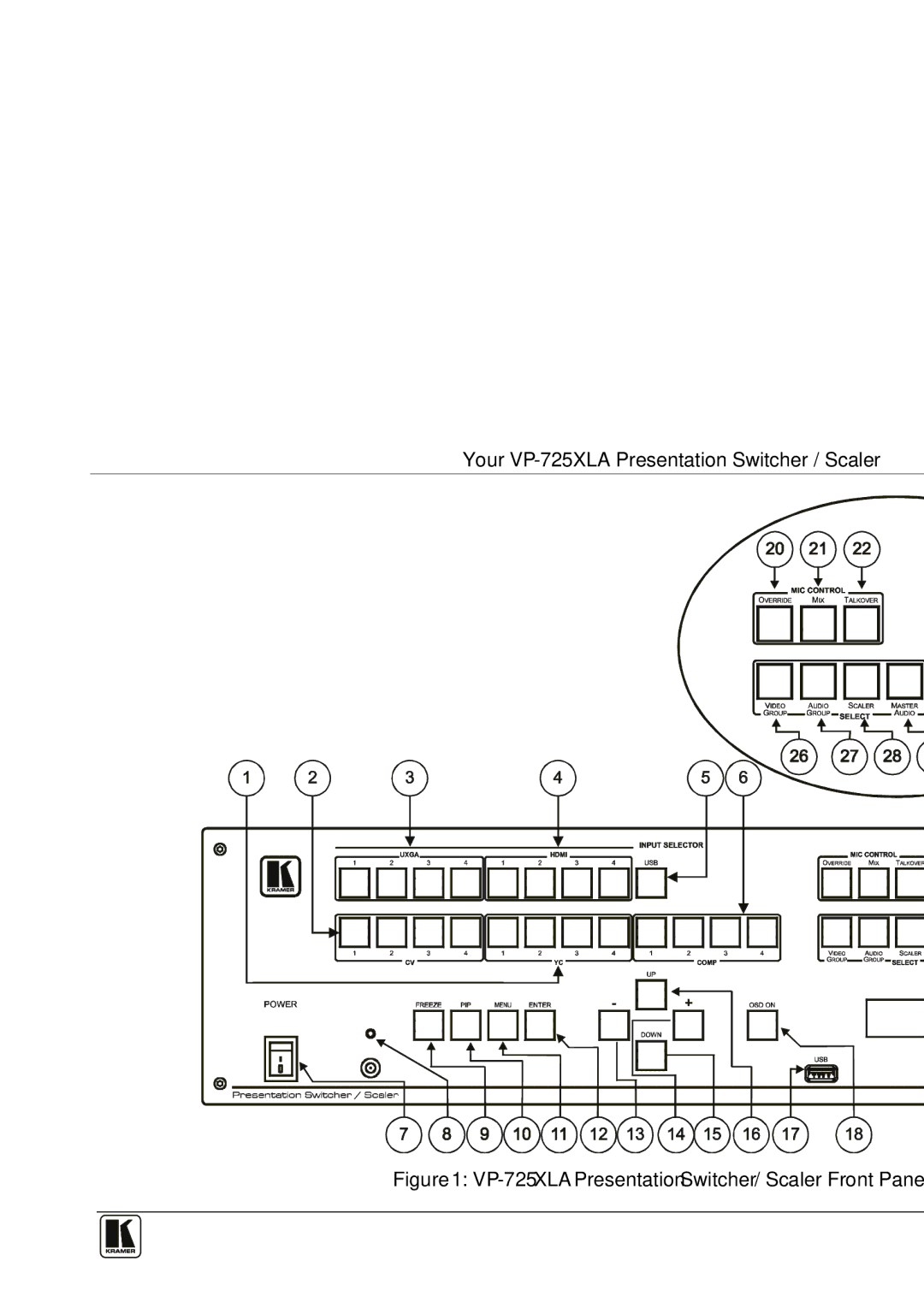
Presentation Switcher / Scaler
Figure 1:
VP-725XLA
Presentation Switcher / Scaler Front Panel
7
Page 10
Page 12
Page 11
Image 11
Page 10
Page 12
Contents
NeVc
Contents
Tables
Figures
Page
Quick Start
Introduction
Getting Started
Kramer Simple Creative Technology
VP-725XLA
Overview
Kramer Simple Creative Technology
Overview
About Hdmi
Your VP-725XLA Presentation Switcher / Scaler
VP-725XLA Presentation Switcher / Scaler Front Panel
Comp
Feature Function
Define the rear panel of the VP-725XLA
VP-725XLA Presentation Switcher / Scaler Rear Panel
Rear Panel VP-725XLA Presentation Switcher / Scaler Features
Installing in a Rack
Connecting the VP-725XLA
Connecting the VP-725XLA Presentation Switcher / Scaler
Connecting the VP-725XLA Presentation Switcher / Scaler
Connecting the VP-725XLA Presentation Switcher / Scaler
Input Color Space
Connecting to the VP-725XLA via RS-232
Rgbs and RGsB PINOUTs
Rgbs and RGsB Pinouts
Straight Cable RS-232 Connection with a Null Modem Adapter
Connecting the VP-725XLA via the Ethernet port
Click OK
Connecting the Balanced/Unbalanced Stereo Audio Input/Output
Using the Operating Modes
Operating the VP-725XLA Presentation Switcher / Scaler
Operation Modes
Switching an Input to an Output
Understanding the Audio Features
Using the Microphone Control Modes
Main Source
Understanding the PIP Feature1
PIP Source Appearance Availability
PIP Source
Displaying a Blank Screen
Locking and Unlocking the Front Panel
Freezing the Image
Configuring the VP-725XLA via the OSD Menu Screens
Configuring and Controlling the VP-725XLA
Input Screen Input Screen Functions
Setting Function Selection/Range Default
Define the Picture screen
Define the Output screen
Define the PIP screen
Define the Audio screen
Audio Level Screen
Defines the settings available for each application
Application Available Settings
Available Settings for Each Application
Slideshow Feature
OSD Functions
Mode Set Functions
Misc Functions
Setting Function Range Default
Input Setup Screen Input Functions
Information Screen
Output Functions
Operating via the LCD Display
Operating via the Infrared Remote Control Transmitter
Key Function
Infrared Remote Control Transmitter Functions
Operating via ETHERNET/Serial Port
Using Text Overlay
Features and Functions of the TextOverlay Application
Using Text Overlay
Technical Specifications1 of the VP-725XLA
Technical Specifications
Standard
Technical Specifications of the Y/C, Video Signal
Resolution Vertical Frequency Hz Remark
Resolution Vertical Remark Frequency Hz
Technical Specifications of the Component Input Signal
Technical Specifications of the HDMI/DVI/RGB Output Signal
11 VP-725XLA Communication Protocol
Communication Protocol of the VP-725XLA
Includes the Communication Protocol
Hdmi
VP-725XLA Communication Protocol
Geometry Diagonal Projection Bottom Right H
VP-725XLA Communication Protocol
Volume- left button
Secam
VP-725XLA Communication Protocol
VP-725XLA Communication Protocol
VP-725XLA Communication Protocol
9 for Get Command 4 for Get Command Be ignore
Error code Description
Error Codes
Error Codes
Limited Warranty
2900-000392 REV 3B
Top
Page
Image
Contents