7
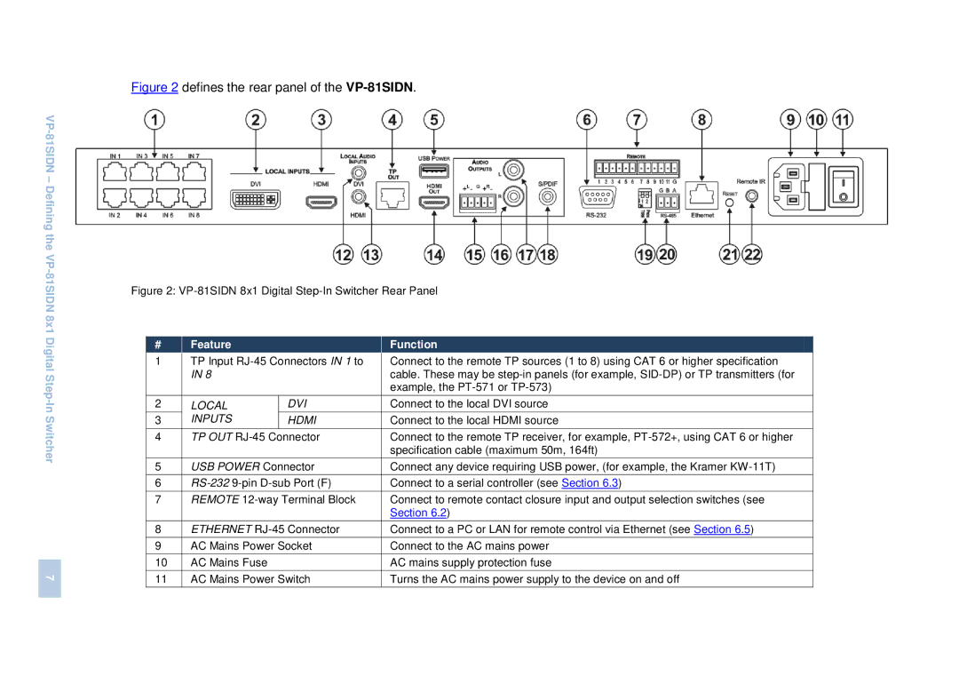
Figure 2 defines the rear panel of the VP-81SIDN.
Figure 2: VP-81SIDN 8x1 Digital Step-In Switcher Rear Panel
# |
| Feature |
|
|
| Function | |||||
1 |
| TP Input |
|
| Connect to the remote TP sources (1 to 8) using CAT 6 or higher specification | ||||||
|
| IN 8 |
|
|
| cable. These may be | |||||
|
|
|
|
|
| example, the | |||||
2 |
| LOCAL | DVI |
|
| Connect to the local DVI source | |||||
3 |
| INPUTS | HDMI |
|
| Connect to the local HDMI source | |||||
|
|
|
|
|
|
|
|
|
|
|
|
4 |
| TP OUT |
|
| Connect to the remote TP receiver, for example, | ||||||
|
|
|
|
|
| specification cable (maximum 50m, 164ft) | |||||
5 |
| USB POWER Connector |
|
| Connect any device requiring USB power, (for example, the Kramer | ||||||
6 |
|
|
| Connect to a serial controller (see Section 6.3) | |||||||
|
|
|
|
|
|
|
|
|
| ||
7 |
| REMOTE |
|
| Connect to remote contact closure input and output selection switches (see | ||||||
|
|
|
|
|
| Section 6.2) | |||||
|
|
|
|
|
|
| |||||
8 |
| ETHERNET |
|
| Connect to a PC or LAN for remote control via Ethernet (see Section 6.5) | ||||||
|
|
|
|
|
|
|
| ||||
9 |
| AC Mains Power Socket |
|
| Connect to the AC mains power | ||||||
|
|
|
|
|
|
| |||||
10 |
| AC Mains Fuse |
|
|
| AC mains supply protection fuse | |||||
11 |
| AC Mains Power Switch |
|
| Turns the AC mains power supply to the device on and off | ||||||