3: Installation of EDS-MD4/8/16 Device Servers
EDS-MD User Guide 24
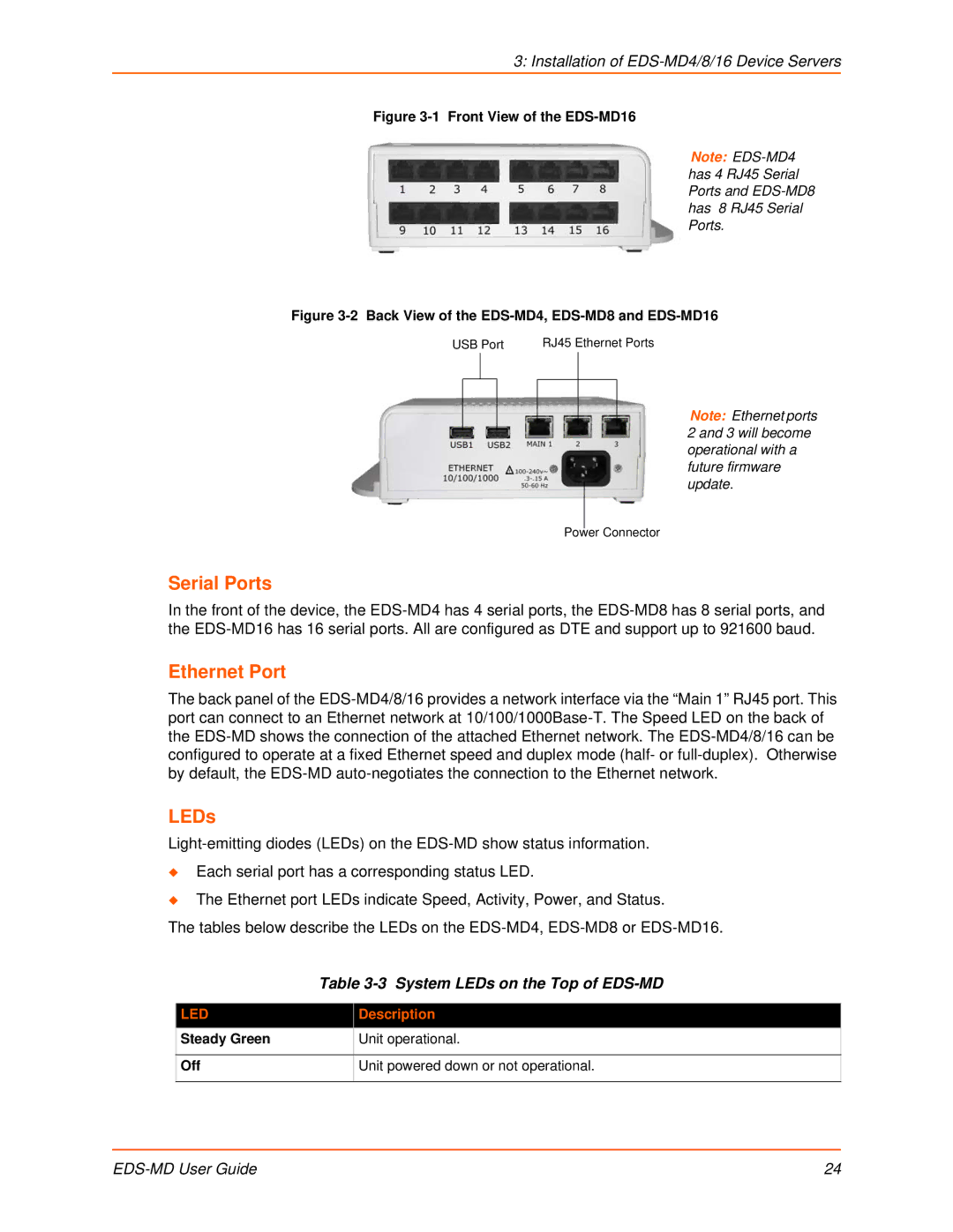
Figure 3-1 Front View of the EDS-MD16
Figure 3-2 Back View of the EDS-MD4, EDS-MD8 and EDS-MD16
Serial Ports
In the front of the device, the EDS-MD4 has 4 serial ports, the EDS-MD8 has 8 serial ports, and
the EDS-MD16 has 16 serial ports. All are configured as DTE and support up to 921600 baud.
Ethernet Port
The back panel of the EDS-MD4/8/16 provides a network interface via the “Main 1” RJ45 port. This
port can connect to an Ethernet network at 10/100/1000Base-T. The Speed LED on the back of
the EDS-MD shows the connection of the attached Ethernet network. The EDS-MD4/8/16 can be
configured to operate at a fixed Ethernet speed and duplex mode (half- or full-duplex). Otherwise
by default, the EDS-MD auto-negotiates the connection to the Ethernet network.
LEDs
Light-emitting diodes (LEDs) on the EDS-MD show status information.
Each serial port has a corresponding status LED.
The Ethernet port LEDs indicate Speed, Activity, Power, and Status.
The tables below describe the LEDs on the EDS-MD4, EDS-MD8 or EDS-MD16.
Table 3-3 System LEDs on the Top of EDS-MD
LED Description
Steady Green Unit operational.
Off Unit powered down or not operational.
Note: EDS-MD4
has 4 RJ45 Serial
Ports and EDS-MD8
has 8 RJ45 Serial
Ports.
RJ45 Ethernet Ports
USB Port
Power Connector
Note: Ethernet ports
2 and 3 will become
operational with a
future firmware
update.