RD120 specifications
The Lenovo RD120 is a robust server specifically designed for small to medium-sized businesses looking for reliable performance and efficiency in their IT infrastructure. This tower server is known for its cost-effectiveness while delivering powerful functionalities that support a wide range of applications, from file sharing to email hosting.One of the main features of the RD120 is its support for Intel's Xeon processors, providing businesses the scalability they need. It can accommodate up to two Xeon processors, enhancing multitasking capabilities and improving overall performance. This makes it suitable for handling various workloads and running multiple applications simultaneously.
In terms of memory, the RD120 supports up to 32GB of DDR3 RAM, offering excellent speed and efficiency for data processing. With multiple DIMM slots available, businesses can upgrade their memory easily depending on their growing needs, ensuring longevity and adaptability for future workloads.
Storage is another strong aspect of the Lenovo RD120. It offers flexible configuration options, supporting up to four hot-swap SATA hard drives and RAID configurations. This means businesses can choose the optimal balance between performance and redundancy, ensuring that data is always safe and accessible. The option for SSDs enhances speed and reliability, catering to data-intensive applications.
Networking capabilities in the RD120 are impressive, with integrated Gigabit Ethernet ports for fast and dependable network connectivity. This feature is crucial for maintaining fast data transfer speeds and ensuring seamless operation across the network.
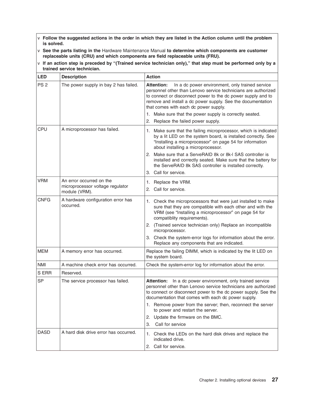
The server’s design is focused on ease of use and management, featuring a tool-less chassis that simplifies upgrades and maintenance. Additionally, Lenovo provides management tools such as the Integrated Management Module, allowing for remote monitoring and administration. This is essential for any business looking to optimize their server performance without the need for constant on-site management.
Security features are built into the RD120, with options for encryption and secure boot firmware. These capabilities help protect sensitive information and maintain system integrity, aligning with business needs in today’s security-conscious environment.
In conclusion, the Lenovo RD120 comprises a blend of power, flexibility, and user-centric design, catering perfectly to the needs of small and medium businesses. Its efficient performance, robust storage options, and management features make it a valuable asset for any organization looking to establish a reliable and scalable IT infrastructure.

