Manuals
/
Liebert
/
Computer Equipment
/
Power Supply
Liebert
user manual
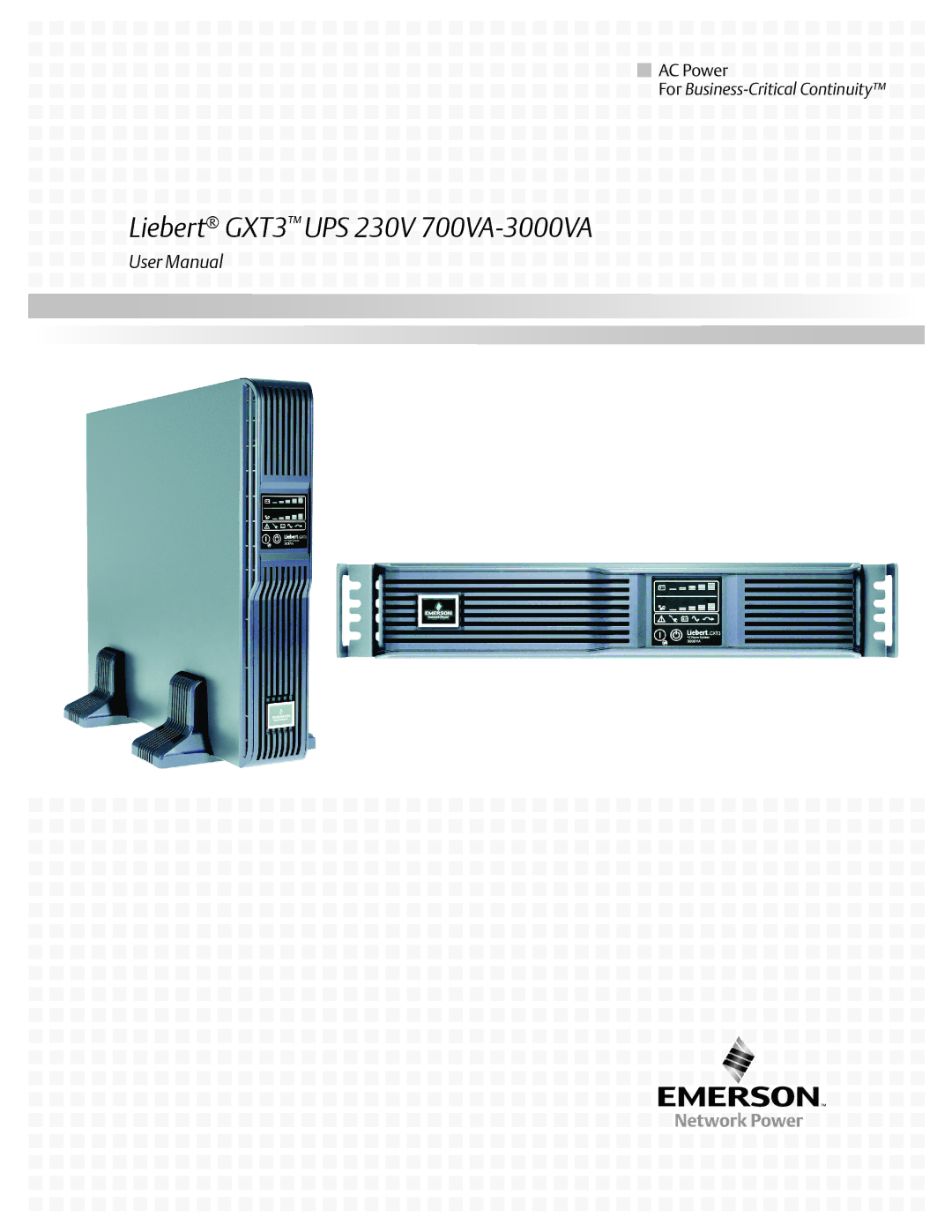
Liebert GXT3 UPS 230V 700VA-3000VA
Models:
GXT3
3000VA
700VA
1
1
44
44
Download
44 pages
44.14 Kb
1
2
3
4
5
6
7
8
<
>
Troubleshooting
Specs
Install
Operating principle diagram
Audible Alarm
Glossary of Symbols
Indicators
Connecting Battery Cables
Warranty
Maintenance
Page 1
Image 1
A
C
P
o
w
er
Fo
r
B
u
si
n
es
s
-C
r
iti
c
al
C
o
n
ti
n
ui
ty
™
Li
e
be
r
t
®
G
XT
3
™
UP
S 2
30
V
7
0
0V
A-30
00
V
A
Us
e
r
M
a
n
u
al
Page 2
Page 1
Image 1
Page 2
Contents
Liebert GXT3 UPS 230V 700VA-3000VA
Page
Table of Contents
Troubleshooting
Maintenance
Operation
Communication
Figures
Page
UPS Safety Notes
Important Safety Precautions
Information for the Protection of the Environment
Battery Safety
Glossary of Symbols
UPS models, power ratings
Features
Model Nominal Power Rating
Available Models
Appearance and Components
Rear Panel Features
Appearance
Ventilation Slots Operation and Display Panel
Major Components
Operating principle diagram
Operating Mode
Battery Mode
Manual Bypass Mode
Battery Recharge Mode
Frequency Converter Mode
Installation
Preparation for Installation
Unpacking and Inspection
What’s Included
Tower Installation
Mechanical Installation
Connectors Spacers Support Bases
Front Plastic Bezel Cover
Liebert GXT3 UPS
Operation and Display Panel Rotated Clockwise 90 Degrees
Pulling inner member from each bracket assembly
Rack Installation
Installing rear member of each bracket assembly
Installing inner members
Connecting Battery Cables
Connecting to AC Mains and Loads
Specification of input circuit breaker
Cable Connection
Connecting USB Communication Cables
Connecting Communication Cables
Control Buttons
1 On/Alarm Silence/Manual Battery Test button
Operation and Display Panel
Standby/Manual Bypass button
Level Indicators Battery Level Indicators
Indicators
Load Level Indicators
UPS status indicators
UPS Status Indicators
UPS Status Indicator Icon Color Description
Manual Battery Test
Startup Checklist for the Liebert GXT3
Starting the UPS
Manual Bypass
Shut Down the Liebert GXT3
Disconnecting Input Power from the Liebert GXT3
Communication
Liebert IntelliSlot Communication Cards
Liebert MultiLink
USB Port Communication
Configuration Program
Output voltage option, all models
Terminal Block Communication
Any Mode Shutdown
On Battery
Battery Mode Shutdown
Low Battery
Maintenance
Replacing the Internal Battery Pack
Battery Replacement Procedures
Replacement battery pack model numbers
Battery Connector
Battery Charging
Internal Battery Pack Handle Pull Out with Battery Handle
Checking UPS Status
Precautions
Checking UPS Functions
Troubleshooting
UPS Symptoms
Indicators
Indicator Diagnosis/Audible alarm
Audible alarm description
Audible Alarm
Troubleshooting table
Condition Alarm
Emerson representative or Emerson Channel Support
Input Breaker External Battery Connector
Battery Cabinet
Specifications of GXT3-700RT230 and GXT3-1000RT230 UPS
Specifications
See Table
Battery run time Recharge Time
Operating temperature parameters
Battery cabinet specifications
Cabinet
Battery run times
Product Warranty Registration
Is t
Ne t
Twor k
Care
Top
Page
Image
Contents


 Liebert® GXT3™ UPS 230V