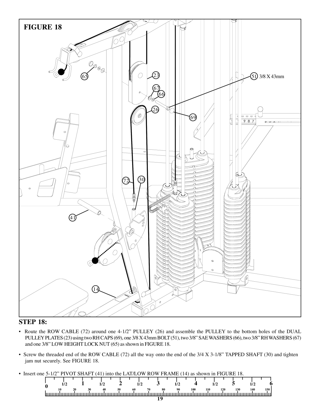
FIGURE 18 | | |
65 | 23 | 51 3/8 X 43mm |
| 67 | |
| 66 | |
| 26 | |
| | 69 |
72 | 30 | |
41 | | |
14 | | |
STEP 18:
•Route the ROW CABLE (72) around one 4-1/2” PULLEY (26) and assemble the PULLEY to the bottom holes of the DUAL PULLEYPLATES (23) using two RH CAPS (69), one 3/8 X 43mm BOLT (51), two 3/8” SAE WASHERS (66), two 3/8” RH WASHERS (67) and one 3/8” LOW HEIGHT LOCK NUT (65) as shown in FIGURE 18.
•Screw the threaded end of the ROW CABLE (72) all the way onto the end of the 3/4 X 3-1/8” TAPPED SHAFT (30) and tighten jam nut securely. See FIGURE 18.
•Insert one 5-1/2” PIVOT SHAFT (41) into the LAT/LOW ROW FRAME (14) as shown in FIGURE 18.
| | | | | | | | | | | | | | | | | | | | | | | | | | | | | | |
0 | 1/2 | | 1 | 1/2 | 2 | 1/2 | 3 | | 1/2 | 4 | | 1/2 | 5 | | 1/2 | 6 |
10 | | 20 | 30 | 40 | 50 | 60 | | 70 | | 80 | 90 | 100 | | 110 | | | 120 | | 130 | 140 | 150 | |
| | | | | | | | |