| 42 |
| 13 |
| 67 |
3/8 X 50mm | 66 |
53 | |
BLACK 68 | |
FIGURE 12 |
|
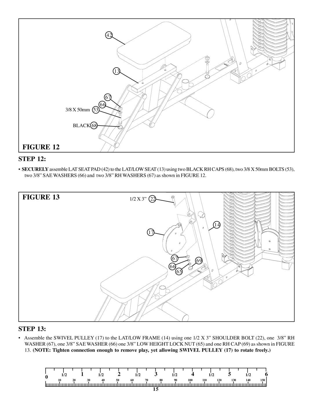
STEP 12:
•SECURELY assemble LAT SEAT PAD (42) to the LAT/LOW SEAT (13) using two BLACK RH CAPS (68), two 3/8 X 50mm BOLTS (53), two 3/8” SAE WASHERS (66) and two 3/8” RH WASHERS (67) as shown in FIGURE 12.
FIGURE 13 | 1/2 X 3” | 22 |
|
|
|
| 14 |
|
| 17 |
|
|
| 67 | 69 |
|
| 66 | |
|
|
| |
|
| 65 |
|
STEP 13:
•Assemble the SWIVEL PULLEY (17) to the LAT/LOW FRAME (14) using one 1/2 X 3” SHOULDER BOLT (22), one 3/8” RH WASHER (67), one 3/8” SAE WASHER (66) one 3/8” LOW HEIGHT LOCK NUT (65) and one RH CAP (69) as shown in FIGURE 13. (NOTE: Tighten connection enough to remove play, yet allowing SWIVEL PULLEY (17) to rotate freely.)
|
|
|
|
|
|
|
|
|
|
|
|
|
|
|
|
|
|
|
|
|
|
|
|
|
|
|
|
|
|
|
|
0 | 1/2 |
| 1 | 1/2 | 2 |
| 1/2 | 3 |
| 1/2 | 4 |
| 1/2 | 5 |
| 1/2 | 6 | ||||||||||||||
10 |
| 20 | 30 | 40 | 50 | 60 |
|
| 70 |
| 80 | 90 | 100 |
| 110 |
|
| 120 |
| 130 | 140 | 150 |
| ||||||||
|
|
|
|
|
|
|
|
|
| ||||||||||||||||||||||
15