17 |
|
|
27 |
|
|
72 |
|
|
26 |
|
|
65 |
| 68 BLACK |
69 |
| |
|
| 67 |
| 46 | 56 3/8 X 70mm |
|
| |
14 | 28 | 66 |
| ||
| 68 BLACK | |
|
| |
51 | 3/8 X 43mm |
|
|
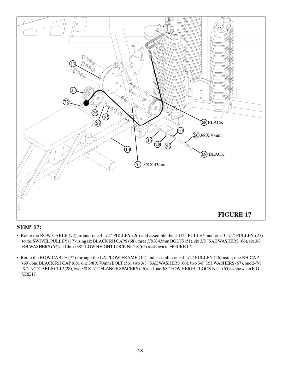
| FIGURE 17 |
STEP 17:
•Route the ROW CABLE (72) around one
•Route the ROW CABLE (72) through the LAT/LOW FRAME (14) and assemble one
18
17 |
|
|
27 |
|
|
72 |
|
|
26 |
|
|
65 |
| 68 BLACK |
69 |
| |
|
| 67 |
| 46 | 56 3/8 X 70mm |
|
| |
14 | 28 | 66 |
| ||
| 68 BLACK | |
|
| |
51 | 3/8 X 43mm |
|
|
| FIGURE 17 |
•Route the ROW CABLE (72) around one
•Route the ROW CABLE (72) through the LAT/LOW FRAME (14) and assemble one
18