STEP 34: |
|
| FIGURE 34 | 94 |
|
|
| |
|
|
|
|
|
| 105 | 109 | |
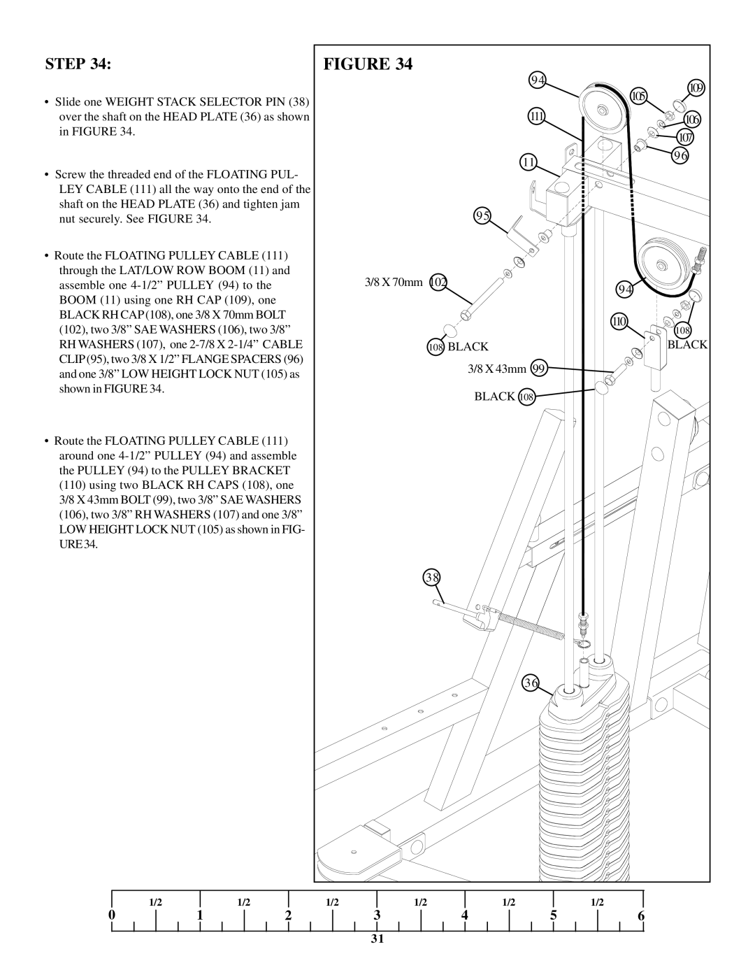
• Slide one WEIGHT STACK SELECTOR PIN (38) |
|
|
|
| ||||
|
|
|
|
| ||||
|
| 111 |
|
|
| |||
over the shaft on the HEAD PLATE (36) as shown |
|
|
|
| 106 | |||
in FIGURE 34. |
|
|
|
|
|
|
| 107 |
|
|
|
|
|
|
|
| |
|
|
|
|
| 11 |
|
| 96 |
• Screw the threaded end of the FLOATING PUL- |
|
|
|
|
| |||
|
|
|
|
|
| |||
LEY CABLE (111) all the way onto the end of the |
|
|
|
|
|
| ||
shaft on the HEAD PLATE (36) and tighten jam |
|
| 95 |
|
|
| ||
nut securely. See FIGURE 34. |
|
|
|
|
|
| ||
• Route the FLOATING PULLEY CABLE (111) |
|
|
|
|
|
| ||
through the LAT/LOW ROW BOOM (11) and |
| 3/8 X 70mm 102 |
|
|
|
| ||
assemble one |
|
|
| 94 |
| |||
BOOM (11) using one RH CAP (109), one |
|
|
|
|
| |||
|
|
|
|
|
| |||
BLACK RH CAP (108), one 3/8 X 70mm BOLT |
|
|
|
| 110 |
| ||
(102), two 3/8” SAE WASHERS (106), two 3/8” |
|
|
|
| 108 | |||
|
|
|
|
| ||||
RH WASHERS (107), one |
| 108 BLACK |
|
| BLACK | |||
CLIP (95), two 3/8 X 1/2” FLANGE SPACERS (96) |
|
| 3/8 X 43mm 99 |
|
|
| ||
and one 3/8” LOW HEIGHT LOCK NUT (105) as |
|
|
|
|
| |||
|
|
|
|
|
| |||
shown in FIGURE 34. |
|
|
|
| BLACK 108 |
|
|
|
|
|
|
|
|
|
|
| |
• Route the FLOATING PULLEY CABLE (111) |
|
|
|
|
|
| ||
around one |
|
|
|
|
|
| ||
the PULLEY (94) to the PULLEY BRACKET |
|
|
|
|
|
| ||
(110) using two BLACK RH CAPS (108), one |
|
|
|
|
|
| ||
3/8 X 43mm BOLT (99), two 3/8” SAE WASHERS |
|
|
|
|
|
| ||
(106), two 3/8” RH WASHERS (107) and one 3/8” |
|
|
|
|
|
| ||
LOW HEIGHT LOCK NUT (105) as shown in FIG- |
|
|
|
|
|
| ||
URE34. |
|
|
|
|
|
|
|
|
|
|
|
| 38 |
|
|
|
|
|
|
|
|
| 36 |
|
|
|
1/2 | 1 | 1/2 | 1/2 | 1/2 | 1/2 | 5 | 1/2 |
|
0 | 2 |
| 3 | 4 | 6 |
| ||
|
|
|
| 31 |
|
|
|
|