TROUBLESHOOTING & REPAIR |
|
Return to Section TOC
Return to Section TOC
Return to Section TOC
Return to Section TOC
Return to Master TOC
Return to Master TOC
Return to Master TOC
Return to Master TOC
WIRE DRIVE ASSEMBLY REMOVAL
PROCEDURE DESCRIPTION
The following procedure will aid in the removal of the entire wire drive unit for possible motor or gear box replacement.
TOOLS REQUIRED
●5/16” nutdriver or socket wrench
●1/4” nutdriver or socket wrench
●Phillips head screwdriver
●Needle nose pliers
●Knife or side cutters
●Screwdriver (slot head)
PROCEDURE
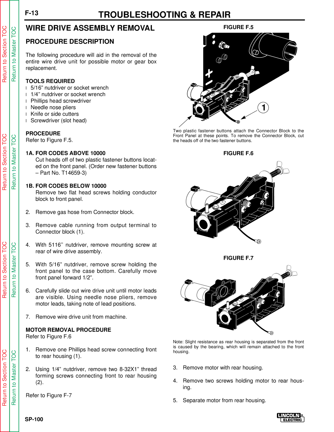
Refer to Figure F.5.
1A. FOR CODES ABOVE 10000
Cut heads off of two plastic fastener buttons locat- ed on the front panel. (Order new fastener buttons
– Part No.
1B. FOR CODES BELOW 10000
Remove two flat head screws holding conductor block to front panel.
2.Remove gas hose from Connector block.
3.Remove cable running from output terminal to Connector block (1).
4.With 5116’’ nutdriver, remove mounting screw at rear of wire drive assembly.
5.With 5/16” nutdriver, remove screw holding the front panel to the case bottom. Carefully move front panel forward 1/2”.
6.Carefully slide out wire drive unit until motor leads are visible. Using needle nose pliers, remove motor leads, taking note of lead positions.
7.Remove wire drive unit from machine.
MOTOR REMOVAL PROCEDURE
Refer to Figure F.6
1.Remove one Phillips head screw connecting front to rear housing (1).
2.Using 1/4” nutdriver, remove two
(2).
Refer to Figure
FIGURE F.5
1
Two plastic fastener buttons attach the Connector Block to the Front Panel at these points. To remove the Connector Block, cut the heads off of the two fastener buttons.
FIGURE F.6
FIGURE F.7
Note: Slight resistance as rear housing is separated from the front is caused by the bearing, which will remain attached to the front housing.
3.Remove motor with rear housing.
4.Remove two screws holding motor to rear hous- ing.
5.Separate motor from rear housing.