| TROUBLESHOOTING & REPAIR |
Return to Section TOC
Return to Section TOC
Return to Section TOC
Return to Master TOC
Return to Master TOC
Return to Master TOC
FAN BLADE AND MOTOR REMOVAL
PROCEDURE DESCRIPTION
The following procedure will aid in the removal and replacement of the fan blade and/or fan motor. It will also provide reasonable access to the output diode heat sinks.
TOOLS REQUIRED
●5/16” nutdriver or socket wrench
●7/16” nutdriver or socket wrench
●7/16” open end wrench
●Phillips head screwdriver
●Needle nose pliers
PROCEDURE
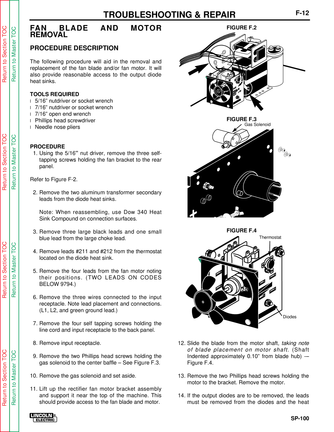
1.Using the 5/16” nut driver, remove the three self- tapping screws holding the fan bracket to the rear panel.
Refer to Figure
2.Remove the two aluminum transformer secondary leads from the diode heat sinks.
Note: When reassembling, use Dow 340 Heat Sink Compound on connection surfaces.
3.Remove three large black leads and one small blue lead from the large choke lead.
4.Remove leads #211 and #212 from the thermostat located on the diode heat sink.
5.Remove the four leads from the fan motor noting their positions. (TWO LEADS ON CODES BELOW 9794.)
6.Remove the three wires connected to the input receptacle. Note lead placement and connections. (L1, L2, and green ground lead.)
7.Remove the four self tapping screws holding the line cord and input receptacle to the back panel.
FIGURE F.2
FIGURE F.3
Gas Solenoid
FIGURE F.4
Thermostat
Diodes
Return to Section TOC
Return to Master TOC
8.Remove input receptacle.
9.Remove the two Phillips head screws holding the gas solenoid to the center baffle – See Figure F.3.
10.Remove the gas solenoid and set aside.
11.Lift up the rectifier fan motor bracket assembly and support it near the top of the machine. This should provide access to the fan blade and motor.
12.Slide the blade from the motor shaft, taking note of blade placement on motor shaft. (Shaft Indented approximately 0.10” from blade hub)
13.Remove the two Phillips head screws holding the motor to the bracket. Remove the motor.
14.If the output diodes are to be removed, the leads must be removed from the diodes and the heat