Return to Section TOC
Return to Section TOC
Return to Section TOC
Return to Section TOC
Return to Master TOC
Return to Master TOC
Return to Master TOC
Return to Master TOC
| TROUBLESHOOTING |
| |||
|
|
|
|
| |
|
|
|
|
|
|
| TROUBLESHOOTING GUIDE - Observe all Safety Guidelines detailed throughout this manual | ||||
|
|
|
|
|
|
| PROBLEMS | POSSIBLE AREAS OF |
| RECOMMENDED |
|
| (SYMPTOMS) | MISADJUSTMENTS(S) |
| COURSE OF ACTION |
|
|
|
|
|
|
|
|
| OUTPUT PROBLEMS |
|
|
|
|
|
|
|
|
|
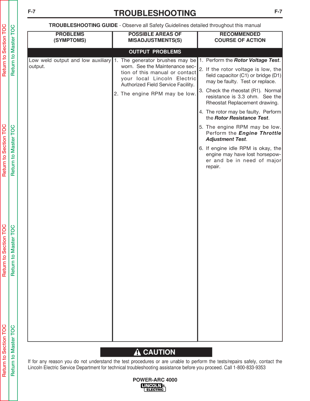
Low weld output and low auxiliary | 1. The generator brushes may be | 1. | Perform the Rotor Voltage Test. |
| |
output. | worn. See the Maintenance sec- | 2. | If the rotor voltage is low, the |
| |
|
| tion of this manual or contact |
| field capacitor (C1) or bridge (D1) |
|
|
| your local Lincoln Electric |
|
| |
|
|
| may be faulty. Test or replace. |
| |
|
| Authorized Field Service Facility. |
|
| |
|
|
|
|
| |
|
| 2. The engine RPM may be low. | 3. | Check the rheostat (R1). Normal |
|
|
|
|
| resistance is 3.3 ohm. See the |
|
|
|
|
| Rheostat Replacement drawing. |
|
|
|
| 4. | The rotor may be faulty. Perform |
|
|
|
|
| the Rotor Resistance Test. |
|
|
|
| 5. | The engine RPM may be low. |
|
|
|
|
| Perform the Engine Throttle |
|
|
|
|
| Adjustment Test. |
|
|
|
| 6. | If engine idle RPM is okay, the |
|
|
|
|
| engine may have lost horsepow- |
|
|
|
|
| er and be in need of major |
|
|
|
|
| repair. |
|
|
|
|
|
|
|
![]() CAUTION
CAUTION
If for any reason you do not understand the test procedures or are unable to perform the tests/repairs safely, contact the Lincoln Electric Service Department for technical troubleshooting assistance before you proceed. Call
