Return to Section TOC
Return to Master TOC
TROUBLESHOOTING & REPAIR | ||
|
| |
|
|
|
STATOR/ROTOR REMOVAL AND REPLACEMENT (continued)
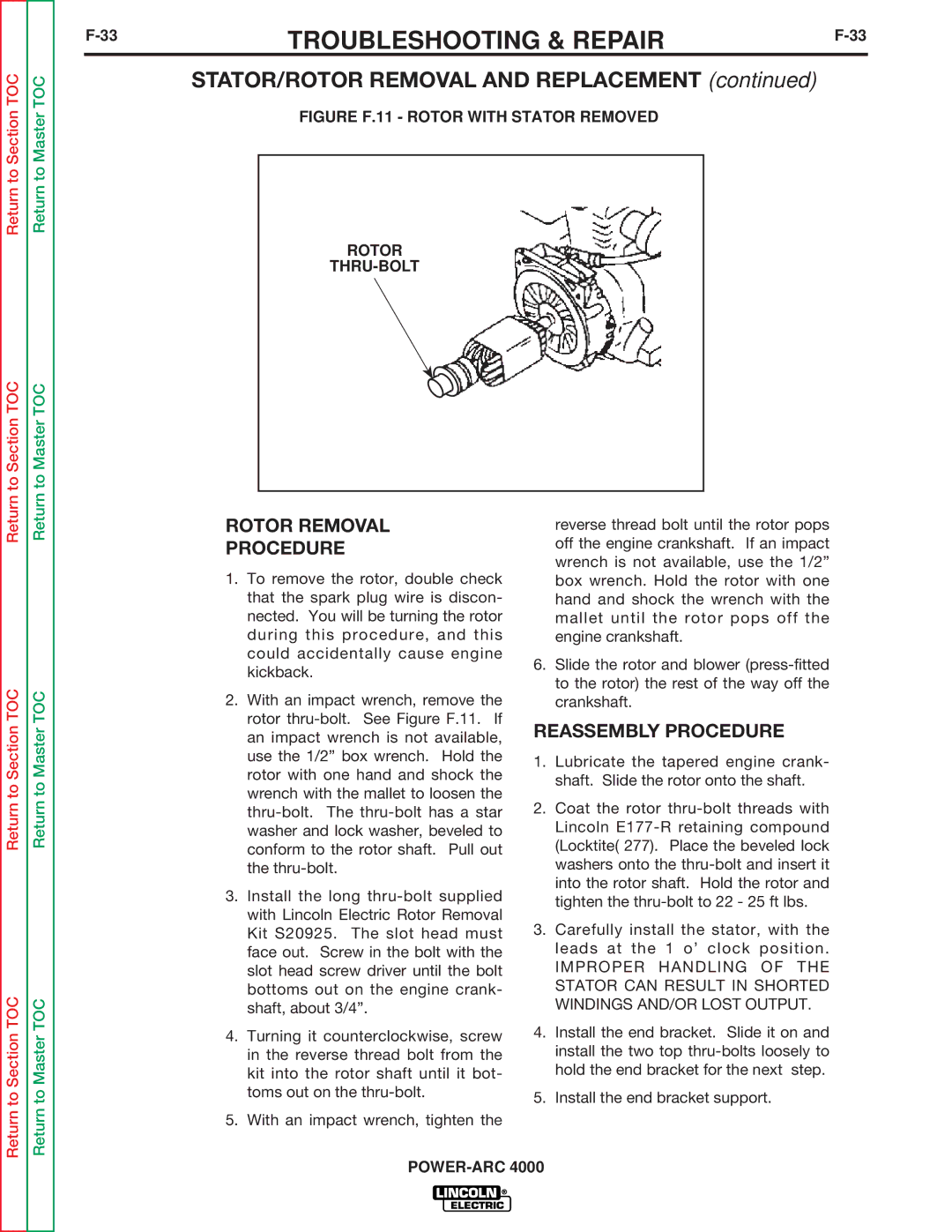
FIGURE F.11 - ROTOR WITH STATOR REMOVED
ROTOR
THRU-BOLT
Return to Section TOC
Return to Section TOC
Return to Section TOC
Return to Master TOC
Return to Master TOC
Return to Master TOC
ROTOR REMOVAL
PROCEDURE
1.To remove the rotor, double check that the spark plug wire is discon- nected. You will be turning the rotor during this procedure, and this could accidentally cause engine kickback.
2.With an impact wrench, remove the rotor
3.Install the long
4.Turning it counterclockwise, screw in the reverse thread bolt from the kit into the rotor shaft until it bot- toms out on the
5.With an impact wrench, tighten the
reverse thread bolt until the rotor pops off the engine crankshaft. If an impact wrench is not available, use the 1/2” box wrench. Hold the rotor with one hand and shock the wrench with the mallet until the rotor pops off the engine crankshaft.
6.Slide the rotor and blower
REASSEMBLY PROCEDURE
1.Lubricate the tapered engine crank- shaft. Slide the rotor onto the shaft.
2.Coat the rotor
3.Carefully install the stator, with the leads at the 1 o’ clock position.
IMPROPER HANDLING OF THE STATOR CAN RESULT IN SHORTED WINDINGS AND/OR LOST OUTPUT.
4.Install the end bracket. Slide it on and install the two top
5.Install the end bracket support.