Manuals
/
Lincoln Electric
/
Power Tools
/
Welder
Lincoln Electric
SVM103-C
service manual
DIAGRAMSG-4
Models:
SVM103-C
1
88
91
91
Download
91 pages
14.16 Kb
84
85
86
87
88
89
90
91
Troubleshooting
Install
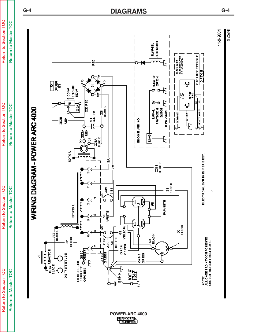
Wiring Diagram Power ARC
SVM Error Reporting Form
Premises Wiring
Dimension
Maintenance
Output Problems
Accessories
Test Procedure
Page 88
Image 88
Return to Section TOC
Return to Section TOC
Return to Section TOC
Return to Section TOC
Return to Master TOC
Return to Master TOC
Return to Master TOC
Return to Master TOC
G-4
DIAGRAMS
G-4
POWER-ARC
4000
Page 87
Page 89
Page 88
Image 88
Page 87
Page 89
Contents
POWER-ARC
Safety Depends on You
Safety
California Proposition 65 Warnings
Electric Shock can kill
Welding Sparks can cause fire or explosion
Précautions DE Sûreté
Master Table of Contents for ALL Sections
Table of Contents Installation Section
Installation
Technical Specifications POWER-ARC
Location and Ventilation
Safety Precautions
Storing
PRE-OPERATION Engine Service
Spark Arrester
Cert. Kool Bore
Electrical Output Connections
Welding Cable Connections
Cable Size for
125 amp
Machine Grounding
Auxiliary Power Receptacles
Plugs and HAND-HELD Equipment
Premises Wiring
Circuit Breakers
These Devices Without
POWER-ARC
Table of Contents Operation Section
Safety Instructions
Operation
Operating Instructions
General Description
Operational Features and Controls
Design Features Advantages
Recommended Applications
Welding Capability
Controls and Settings
GENERATOR/WELDER Controls
Gasoline Engine Controls
20 AMP, 120 Volt Duplex Receptacle
Before Starting the Engine
Engine Operation
Starting the Engine
For a HOT Engine
Generator Operation
To USE the Generator AS AN Auxiliary Power Supply
General Information
Table B.1 Generator Power Applications
Suggested Power Applications Running Watts Start-up Watts
Welding Operation
Welding Guidelines
Table B.2 Welding APPLICATIONS/ELECTRODE Selection Guide
Operation
What Happens in the Arc?
Correct Welding Position Correct Arc Length
Practice
Use the following
Do the following
Butt Welds
Fillet Welds
Penetration
Vertical-Up Welding
Vertical-Down Welding
Hardfacing To Reduce Wear
Overhead Welding
Welding Sheet Metal
Welding Cast Iron
Cast Iron Plate Preparation
Out-of-Position Group AWS E6011
High-Speed Group AWS E6013
Low Hydrogen Group Stable-Arc E7018
Table of Contents Accessories Section
OPTIONS/ACCESSORIES
Accessories
Lincoln Electric Accessories
Table of Contents Maintenance Section
Maintenance
Routine and Periodic Maintenance
Engine Maintenance
Engine Adjustments
Figure D.2 Clean Rotating SCREEN/FINGER GUARD/DEBRIS Guard
Table D.1 Engine Maintenance Schedule
GENERATOR/WELDER Maintenance
Do not attempt to polish slip rings while engine is running
Figure D.6. Major Component Locations
Table of Contents Theory of Operation Section
Theory of Operation
ENGINE, EXCITATION, Rotor and Stator
Rotor Field Feedback and Auxiliary Power
Figure E.3 Field Excitation and Auxiliary Power
Auxiliary Power Overcurrent Protection
Weld Winding and Reactor
Table of Contents Troubleshooting & Repair Section
Troubleshooting & Repair
HOW to USE Troubleshooting Guide
Troubleshooting
Output Problems
Electric Authorized Field Ser
Or contact your local Lincoln
Vice Facility
Field Service Facility
Local Lincoln Electric Authorized
Troubleshooting
Rotor Resistance Test
Engine Problems
Troubleshooting
Engine Throttle Adjustment
This procedure takes approximately 15 minutes to perform
Rotor Voltage Test
Test Description
Materials Needed
Test Procedure
Rotor Voltage Test
This procedure takes approximately 25 minutes to perform
Rotor Resistance Test
Rotor Resistance Test
Figure F.3 Brushes Retained with Cable TIE
Engine Throttle Adjustment Test
This procedure takes approximately 20 minutes to perform
Frequency Counter Method
Strobe-tach Method
Oscilloscope Method
Wing NUT High Speed Stop Screw
Normal Open Circuit Weld Voltage Waveform
Scope Settings
High Idle no Load
Normal Open Circuit Voltage Waveform 115 VAC Supply
Machine Loaded
Typical Weld Output Waveform
Machine Loaded to 125 Amps AT 23 VAC
Brush Removal and Replacement
Description
Brush Removal and Replacement
Procedure
Procedure
Rheostat Removal and Replacement
Figure F.7 Rheostat Removal
Capacitor AND/OR Diode Bridge Removal and Replacement
This procedure takes approximately 35 minutes to perform
Procedure Capacitor Removal and REPLACE- Ment
Figure F.8 Location and Discharging the Field Capacitor
Procedure Field Diode Bridge Removal and Replacement
Figure F.8A Field Diode Bridge Location
This procedure takes approximately 3 hours to perform
STATOR/ROTOR Removal and Replacement
Instructions
STATOR/ROTOR Removal and Replacement
Troubleshooting & Repair
Rotor Removal Procedure
Figure F.12 Checking ROTOR-STATOR AIR GAP
Auxiliary Power Receptacle OUTPUT1
Retest After Repair
Engine Output
WELDER/GENERATOR OUTPUT1
Return to Section TOC
Table of Contents Diagrams Section
Diagrams
Wiring Diagram Power ARC
DIAGRAMSG-3
DIAGRAMSG-4
Dimension Print Power ARC
Return to Section TOC
SVM Error Reporting Form
Top
Page
Image
Contents