TOC
TOC
| INSTALLATION | ||||
|
|
|
|
|
|
Cable Installation |
|
|
|
| |
|
| WARNING |
| ||
|
|
|
|
| |
Return to Master
Return to Master TOC
Return to Master TOC
Return to Master TOC
Install the welding cables to your
1.The gasoline engine must be OFF to install weld- ing cables.
2.Remove the 1/2 - 13 flanged nuts from the output terminals.
3.Connect the electrode holder and work cables to the weld output terminals. You can connect either cable to either terminal, since the POWER- ARC 4000 provides AC weld current.
4.Tighten the flanged nuts securely.
5.Be certain that the metal piece you are welding (the “work”) is securely connected to the work clamp and cable.
6.Check and tighten the connections periodically.
CAUTION
•Loose connections will cause the output terminals to overheat. The terminals may eventually melt.
•Do not cross the welding cables at the output termi- nal connection. Keep the cables isolated and sepa- rate from one another.
Lincoln Electric offers a welding accessory kit with the properly specified welding cables. See the ACCESSORIES section of this manual for more infor- mation.
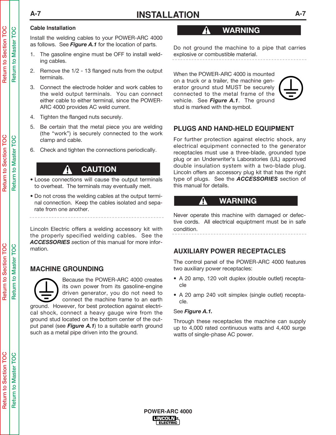
MACHINE GROUNDING
Because the
ground. However, for best protection against electri- cal shock, connect a heavy gauge wire from the ground stud located on the bottom center of the out- put panel (see Figure A.1) to a suitable earth ground such as a metal pipe driven into the ground.
Do not ground the machine to a pipe that carries explosive or combustible material.
When the
PLUGS AND HAND-HELD EQUIPMENT
For further protection against electric shock, any electrical equipment connected to the generator receptacles must use a
WARNING
Never operate this machine with damaged or defec- tive cords. All electrical equiptment must be in safe condition.
AUXILIARY POWER RECEPTACLES
The control panel of the
•A 20 amp, 120 volt duplex (double outlet) recepta- cle
•A 20 amp 240 volt simplex (single outlet) recepta- cle.
See Figure A.1.
Through these receptacles the machine can supply up to 4,000 rated continuous watts and 4,400 surge watts of