TOC

TOC

E-5

E-5

THEORY OF OPERATION

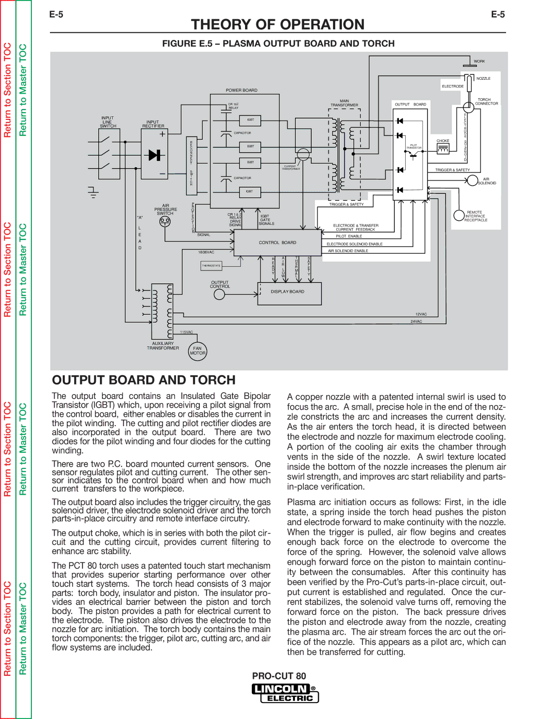
FIGURE E.5 – PLASMA OUTPUT BOARD AND TORCH

Return to Section

Return to Master

INPUT


LINE

INPUT

SWITCH

RECTIFIER


AIR


PRESSURE


SWITCH


"A"

POWER BOARD

CR 1&2

RELAY

IGBT

CAPACITOR

R

EIGBT

C

O


N


N


E


C


IGBT


T


CURRENT


S


TRANSFORMER


W


I


CAPACITOR


T


C


H


IGBT


P


R


O


T

CR 1

& 2

IGBT

E

RELAY

C

GATE

DRIVE

T

SIGNALS

MAIN

TRANSFORMER

TRIGGER & SAFETY


WORK


NOZZLE


ELECTRODE


TORCH

OUTPUT

BOARD

CONNECTOR


E


L


E


C


T


R


O


D


E


CHOKE

S


PILOT

O

TRANSISTOR

L

E


N


O


I


D


TRIGGER & SAFETY


AIR


SOLENOID


REMOTE


INTERFACE


RECEPTACLE

Return to Section TOC

Return to Master TOC

L

E

A

D

I


SIGNAL


O


N

SIGNAL


CONTROL BOARD


18/36VAC


R

A

T

S


E

I

H

A


R

E

F


THERMOSTATS


A


L

R

E


D

M

T


Y

O

A

Y


W

L


OUTPUT CONTROL

DISPLAY BOARD

ELECTRODE & TRANSFER

CURRENT FEEDBACK

PILOT ENABLE

ELECTRODE SOLENOID ENABLE

AIR SOLENOID ENABLE

12VAC

24VAC

115VAC

AUXILIARY

TRANSFORMER FAN MOTOR

Return to Section TOC

Return to Section TOC

Return to Master TOC

Return to Master TOC

OUTPUT BOARD AND TORCH

The output board contains an Insulated Gate Bipolar Transistor (IGBT) which, upon receiving a pilot signal from the control board, either enables or disables the current in the pilot winding. The cutting and pilot rectifier diodes are also incorporated in the output board. There are two diodes for the pilot winding and four diodes for the cutting winding.

There are two P.C. board mounted current sensors. One sensor regulates pilot and cutting current. The other sen- sor indicates to the control board when and how much current transfers to the workpiece.

The output board also includes the trigger circuitry, the gas solenoid driver, the electrode solenoid driver and the torch parts-in-place circuitry and remote interface circutry.

The output choke, which is in series with both the pilot cir- cuit and the cutting circuit, provides current filtering to enhance arc stability.

The PCT 80 torch uses a patented touch start mechanism that provides superior starting performance over other touch start systems. The torch head consists of 3 major parts: torch body, insulator and piston. The insulator pro- vides an electrical barrier between the piston and torch body. The piston provides a path for electrical current to the electrode. The piston also drives the electrode to the nozzle for arc initiation. The torch body contains the main torch components: the trigger, pilot arc, cutting arc, and air flow systems are included.

A copper nozzle with a patented internal swirl is used to focus the arc. A small, precise hole in the end of the noz- zle constricts the arc and increases the current density. As the air enters the torch head, it is directed between the electrode and nozzle for maximum electrode cooling. A portion of the cooling air exits the chamber through vents in the side of the nozzle. A swirl texture located inside the bottom of the nozzle increases the plenum air swirl strength, and improves arc start reliability and parts- in-place verification.

Plasma arc initiation occurs as follows: First, in the idle state, a spring inside the torch head pushes the piston and electrode forward to make continuity with the nozzle. When the trigger is pulled, air flow begins and creates enough back force on the electrode to overcome the force of the spring. However, the solenoid valve allows enough forward force on the piston to maintain continu- ity between the consumables. After this continuity has been verified by the Pro-Cut’s parts-in-place circuit, out- put current is established and regulated. Once the cur- rent stabilizes, the solenoid valve turns off, removing the forward force on the piston. The back pressure drives the piston and electrode away from the nozzle, creating the plasma arc. The air stream forces the arc out the ori- fice of the nozzle. This appears as a pilot arc, which can then be transferred for cutting.

PRO-CUT 80

Page 35
Image 35
Lincoln Electric SVM146-A service manual Figure E.5 Plasma Output Board and Torch

SVM146-A specifications

Lincoln Electric's SVM146-A is a versatile and powerful multi-process welding machine designed for professionals in various industries. Known for its robustness and reliability, this machine excels in both performance and user-friendly features, making it a popular choice among welders.

One of the standout features of the SVM146-A is its multi-process capability, allowing users to perform MIG, TIG, and stick welding using a single unit. This versatility is enhanced by Lincoln Electric's innovative Auto-Set technology, which automatically adjusts the machine's settings based on the selected process and materials being welded. This feature significantly reduces the time spent on setup and helps ensure optimal weld quality, even for less experienced operators.

The SVM146-A is powered by a reliable inverter design, which provides greater efficiency compared to traditional transformer-based machines. This compact and lightweight design allows for easy transport, making it ideal for job sites or remote locations. The inverter technology also contributes to enhanced arc stability and better overall performance, providing high-quality welds in less time.

Another key characteristic of this welding machine is its robust construction, designed to withstand the rigors of heavy industrial use. The SVM146-A features a durable chassis and control panel, ensuring longevity and reliability under challenging working conditions. Additionally, its intuitive interface allows users to easily navigate settings and make adjustments as needed.

Safety is a paramount concern in welding applications, and the SVM146-A is equipped with several safety features, including over-temperature and over-voltage protection, ensuring that the machine operates safely even in demanding environments. It also features a start inhibit system, preventing the machine from being started under unsafe conditions.

The SVM146-A is compatible with a variety of welding accessories and consumables, enhancing its flexibility and usability across different applications. Whether it’s automotive repair, heavy fabrication, or maintenance work, this welding machine adapts to various tasks, making it a valuable addition to any professional's toolkit.

In conclusion, Lincoln Electric's SVM146-A stands out as a multi-process welding machine that combines advanced technology, robust design, and user-friendly features. It is engineered for performance and reliability, making it an excellent investment for professionals dedicated to achieving high-quality welds.