|
|
|
|
| THEORY OF OPERATION |
| ||||||||
|
|
|
|
|
|
|
|
|
|
|
|
| ||
TOC | TOC |
|
|
| FIGURE E.2 - ENGINE COMPONENTS AND OPERATION |
| ||||||||
|
|
|
|
|
|
| SWITCH |
|
|
|
| |||
|
|
|
|
|
|
|
|
| RANGE |
|
|
|
| |
Section | Master |
|
|
|
|
|
|
|
|
| 254 |
| TOROID* | |
|
|
|
|
|
| S2 | E |
|
|
|
| ELECTRODE | ||
|
|
|
|
|
|
|
|
|
|
|
| |||
|
|
|
|
|
|
|
|
|
| AC |
|
| ||
| to |
|
|
|
|
|
|
|
|
|
|
| ||
to |
|
|
|
|
|
|
|
|
|
|
| TERMINAL | ||
|
|
|
|
| REACTOR |
|
| OUTPUT + |
| |||||
|
|
|
|
|
|
| CHOKE | POLARITY | ||||||
Return | Return |
|
|
|
|
|
|
| ||||||
|
|
|
|
|
|
|
|
|
|
| WORK | |||
|
|
|
|
|
|
|
|
|
|
| AC BRIDGE |
| SWITCH | |
|
|
|
|
| FUEL |
| W2 |
| C1 WAC | W1 |
|
|
| TERMINAL |
|
| STARTER |
|
|
|
|
|
|
| |||||
|
|
| SHUTOFF |
|
|
|
|
|
|
|
|
| ||
|
| SOLENOID |
| SOLENOID |
|
|
|
|
|
|
|
|
| |
|
|
|
|
|
|
|
| WELD WINDINGS |
|
|
|
| ||
|
|
|
|
| STARTER | MECHANICAL |
|
|
|
|
| AUXILIARY |
| |
|
|
|
|
|
|
|
|
|
| WINDINGS |
| |||
|
|
|
|
|
| ROTAT ION |
|
|
|
|
|
|
|
|
|
|
|
|
| ENGINE |
| SLIP | ROTOR | STATOR | Z | Y |
| ||
|
|
|
|
|
|
| 3 |
| ||||||
|
|
|
| FLYWHEEL ALTERNATOR/ |
| RINGS |
|
|
|
|
|
| ||
|
|
|
|
|
|
|
|
|
|
| 5 |
| ||
|
|
|
|
| VOLTAGE REGULATOR |
|
|
|
|
|
|
|
| |
TOC | TOC |
|
|
|
| SOLENOID | 7 | EXCITER | 9 |
|
|
| 6 |
|
|
|
|
| WINDING |
|
|
| X |
| |||||
Section | Master |
|
|
|
| IDLER |
|
|
|
|
|
|
| |
| CONTROL | 3 |
| DIODE |
|
| 3 6 X |
| TOROID* |
|
| |||
|
|
| 4 |
| OIL |
|
|
|
|
|
|
|
|
|
|
| 1 |
|
| PRESSURE |
|
|
|
|
|
|
|
|
|
|
| ENGINE |
| SWITCH |
| FLASHING |
|
|
|
|
|
|
| |
| to |
|
|
|
|
|
|
|
|
|
|
| ||
to |
| SWITCH* | 2 | HOUR |
|
|
|
|
|
|
|
|
| |
Return | Return |
| + | - |
| FIELD |
|
|
|
|
|
| Z X Y | |
|
|
|
|
|
|
|
|
|
|
|
|
| ||
|
|
|
|
|
|
|
|
|
|
|
|
|
| |
|
|
|
|
|
|
| CAPACITOR |
|
|
|
|
|
|
|
|
|
|
|
| METER |
|
|
|
|
|
|
|
|
|
|
|
| BATTERY | OUTPUT |
|
| 120 & 230 VOLT |
|
| 480 VOLT 3 PHASE | ||||
|
|
| CONTROL |
|
|
|
| |||||||
|
|
|
|
|
|
|
|
| BREAKERS AND |
|
| BREAKER AND | ||
|
|
|
|
|
|
|
|
| RECEPTACLES |
|
| RECEPTACLE | ||
|
|
|
|
|
|
|
| * Lead 254 - 1 turn through the toroid | ||
|
|
|
|
|
|
| PRINTED CIRCUIT | Leads 3 & 6 - two turns through the toroid in opposite directions. | ||
|
|
|
|
|
|
| BOARD | Lead X passes though the toroid in the same direction as lead 6 | ||
TOC | TOC | GENERAL DESCRIPTION |
|
|
| |||||
|
|
|
|
|
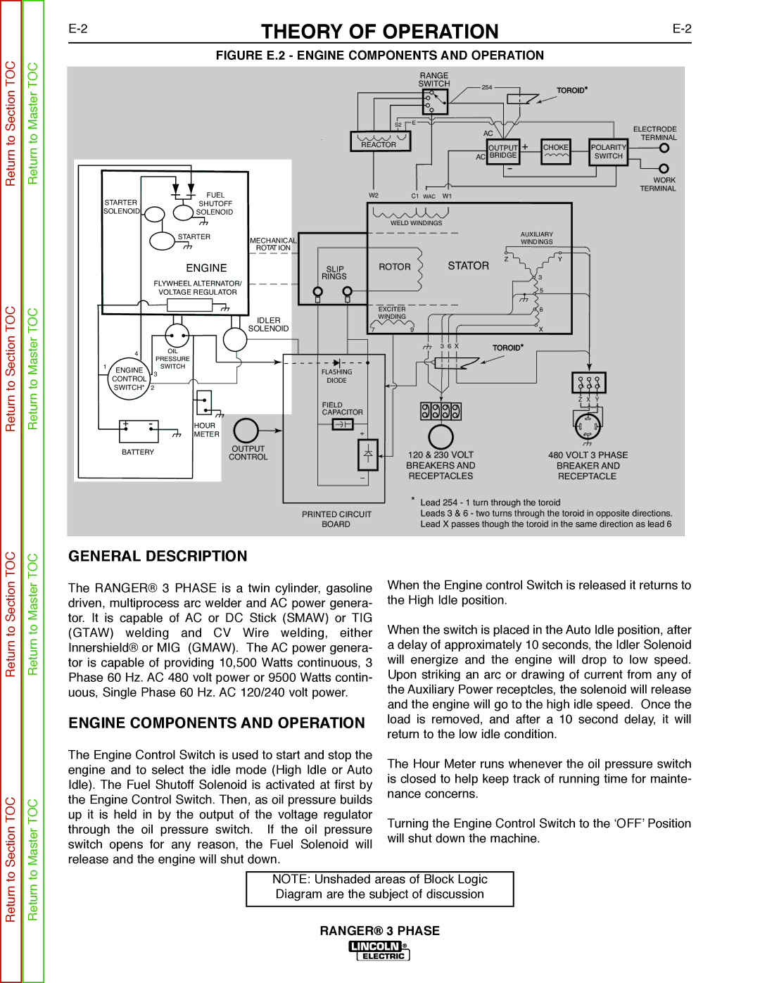
| When the Engine control Switch is released it returns to | ||||
Section | Master | The RANGER® 3 PHASE is a twin cylinder, gasoline | ||||||||
tor. It is capable of AC or DC Stick (SMAW) or TIG | the High Idle position. | |||||||||
|
| driven, multiprocess arc welder and AC power genera- | ||||||||
to | to | (GTAW) | welding | and | CV Wire | welding, either | When the switch is placed in the Auto Idle position, after | |||
Return | Return | Innershield® or MIG | (GMAW). The AC power genera- | a delay of approximately 10 seconds, the Idler Solenoid | ||||||
|
| tor is capable of providing 10,500 Watts continuous, 3 | will energize and the engine will drop to low speed. | |||||||
|
| Phase 60 Hz. AC 480 volt power or 9500 Watts contin- | Upon striking an arc or drawing of current from any of | |||||||
|
| uous, Single Phase 60 Hz. AC 120/240 volt power. | the Auxiliary Power receptcles, the solenoid will release | |||||||
|
|
|
|
|
|
|
| and the engine will go to the high idle speed. Once the | ||
|
| ENGINE COMPONENTS AND OPERATION | load is removed, and after a 10 second delay, it will | |||||||
|
| return to the low idle condition. | ||||||||
|
|
|
|
|
|
|
| |||
|
| The Engine Control Switch is used to start and stop the | The Hour Meter runs whenever the oil pressure switch | |||||||
|
| engine and to select the idle mode (High Idle or Auto | ||||||||
|
| is closed to help keep track of running time for mainte- | ||||||||
|
| Idle). The Fuel Shutoff Solenoid is activated at first by | ||||||||
|
| nance concerns. | ||||||||
TOC | TOC | the Engine Control Switch. Then, as oil pressure builds | ||||||||
|
| |||||||||
up it is held in by the output of the voltage regulator | Turning the Engine Control Switch to the ‘OFF’ Position | |||||||||
|
| |||||||||
Sectionto | Masterto | through | the oil pressure | switch. If | the oil pressure | |||||
will shut down the machine. | ||||||||||
switch opens for any reason, the Fuel Solenoid will | ||||||||||
|
| |||||||||
|
|
|
| |||||||
|
| release and the engine will shut down. |
|
| ||||||
|
|
|
|
|
|
| ||||
Return | Return |
|
|
|
| NOTE: Unshaded areas of Block Logic |
| |||
|
|
|
|
| Diagram are the subject of discussion |
| ||||
|
|
|
|
|
|
|
| |||
|
|
|
|
|
|
|
|
| ||
|
|
|
|
|
|
| RANGER® 3 PHASE | |||