|
|
|
|
| THEORY OF OPERATION |
| ||||||||
|
|
|
|
|
|
|
|
|
|
|
|
| ||
TOC | TOC |
|
|
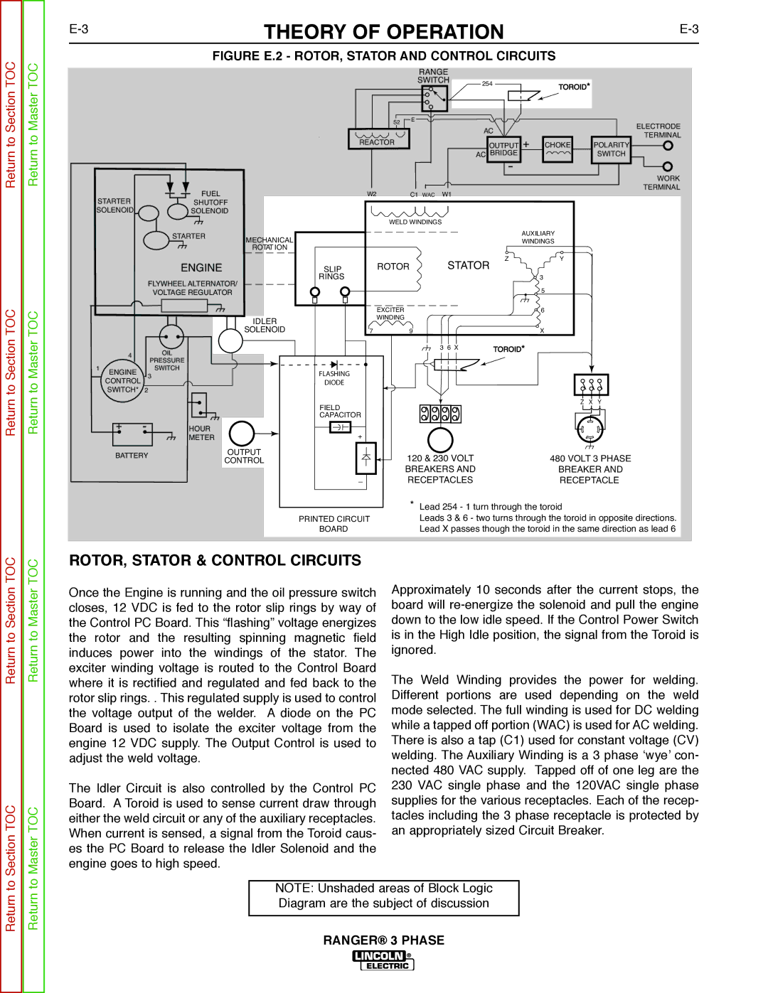
| FIGURE E.2 - ROTOR, STATOR AND CONTROL CIRCUITS |
| ||||||||
|
|
|
|
|
|
| RANGE |
|
|
|
| |||
|
|
|
|
|
|
| SWITCH | 254 | TOROID* | |||||
Section | Master |
|
|
|
|
|
|
|
|
|
|
| ||
|
|
|
|
|
| S2 | E |
|
|
|
| ELECTRODE | ||
|
|
|
|
|
|
|
|
|
|
|
|
| ||
|
|
|
|
|
|
|
|
|
| AC |
|
| ||
to | to |
|
|
|
|
|
|
|
|
|
| TERMINAL | ||
|
|
|
|
| REACTOR |
|
| OUTPUT + |
| |||||
|
|
|
|
|
|
| CHOKE | POLARITY | ||||||
Return | Return |
|
|
|
|
|
|
|
|
| AC | BRIDGE |
| SWITCH |
|
|
|
|
|
|
|
|
|
|
| WORK | |||
|
|
|
|
|
|
|
|
|
|
|
|
| ||
|
|
|
|
|
|
|
|
|
|
|
|
|
| |
|
|
|
|
| FUEL |
| W2 |
| C1 WAC | W1 |
|
|
| TERMINAL |
|
| STARTER |
|
|
|
|
|
|
| |||||
|
|
| SHUTOFF |
|
|
|
|
|
|
|
|
| ||
|
| SOLENOID |
| SOLENOID |
|
|
|
|
|
|
|
|
| |
|
|
|
|
|
|
|
| WELD WINDINGS |
|
|
|
| ||
|
|
|
|
| STARTER | MECHANICAL |
|
|
|
|
| AUXILIARY |
| |
|
|
|
|
|
|
|
|
|
| WINDINGS |
| |||
|
|
|
|
|
| ROTAT ION |
|
|
|
|
|
|
|
|
|
|
|
|
| ENGINE |
| SLIP | ROTOR | STATOR | Z | Y |
| ||
|
|
|
|
|
|
| 3 |
| ||||||
|
|
|
| FLYWHEEL ALTERNATOR/ |
| RINGS |
|
|
|
|
|
| ||
|
|
|
|
|
|
|
|
|
|
| 5 |
| ||
|
|
|
|
| VOLTAGE REGULATOR |
|
|
|
|
|
|
|
| |
TOC | TOC |
|
|
|
| SOLENOID | 7 | EXCITER | 9 |
|
|
| 6 |
|
|
|
|
| WINDING |
|
|
| X |
| |||||
Section | Master |
|
|
|
| IDLER |
|
|
|
|
|
|
| |
| CONTROL | 3 |
| DIODE |
|
| 3 6 X |
| TOROID* |
|
| |||
|
|
| 4 |
| OIL |
|
|
|
|
|
|
|
|
|
|
| 1 |
|
| PRESSURE |
|
|
|
|
|
|
|
|
|
|
| ENGINE |
| SWITCH |
| FLASHING |
|
|
|
|
|
|
| |
|
|
|
|
|
|
|
|
|
|
|
|
| ||
to | to |
| SWITCH* | 2 | HOUR |
|
|
|
|
|
|
|
|
|
Return | Return |
| + | - |
| FIELD |
|
|
|
|
|
| Z X Y | |
|
|
|
|
|
|
|
|
|
|
|
|
| ||
|
|
|
|
|
|
|
|
|
|
|
|
|
| |
|
|
|
|
|
|
| CAPACITOR |
|
|
|
|
|
|
|
|
|
|
|
| METER |
|
|
|
|
|
|
|
|
|
|
|
| BATTERY | OUTPUT |
|
| 120 & 230 VOLT |
|
| 480 VOLT 3 PHASE | ||||
|
|
|
|
| CONTROL |
|
|
|
| |||||
|
|
|
|
|
|
|
|
| BREAKERS AND |
|
| BREAKER AND | ||
|
|
|
|
|
|
|
|
| RECEPTACLES |
|
| RECEPTACLE | ||
|
|
|
| * Lead 254 - 1 turn through the toroid | |
|
|
| PRINTED CIRCUIT | Leads 3 & 6 - two turns through the toroid in opposite directions. | |
|
|
| BOARD | Lead X passes though the toroid in the same direction as lead 6 | |
TOC | TOC | ROTOR, STATOR & CONTROL CIRCUITS |
|
| |
|
| Approximately 10 seconds after the current stops, the | |||
Section | Master | Once the Engine is running and the oil pressure switch | |||
the Control PC Board. This “flashing” voltage energizes | down to the low idle speed. If the Control Power Switch | ||||
|
| closes, 12 VDC is fed to the rotor slip rings by way of | board will | ||
to | to | the rotor and the resulting spinning magnetic field | is in the High Idle position, the signal from the Toroid is | ||
Return | Return | induces power into the windings of the stator. The | ignored. | ||
where it is rectified and regulated and fed back to the | The Weld Winding provides the power for welding. | ||||
|
| exciter winding voltage is routed to the Control Board |
|
| |
|
| rotor slip rings. . This regulated supply is used to control | Different portions are used depending on the weld | ||
|
| the voltage output of the welder. A diode on the PC | mode selected. The full winding is used for DC welding | ||
|
| Board is used to isolate the exciter voltage from the | while a tapped off portion (WAC) is used for AC welding. | ||
|
| engine 12 VDC supply. The Output Control is used to | There is also a tap (C1) used for constant voltage (CV) | ||
|
| adjust the weld voltage. | welding. The Auxiliary Winding is a 3 phase ‘wye’ con- | ||
|
|
|
| nected 480 VAC supply. Tapped off of one leg are the | |
|
| The Idler Circuit is also controlled by the Control PC | 230 VAC single phase and the 120VAC single phase | ||
TOC | TOC | Board. A Toroid is used to sense current draw through | supplies for the various receptacles. Each of the recep- | ||
either the weld circuit or any of the auxiliary receptacles. | tacles including the 3 phase receptacle is protected by | ||||
Sectionto | Masterto | When current is sensed, a signal from the Toroid caus- | an appropriately sized Circuit Breaker. | ||
es the PC Board to release the Idler Solenoid and the |
|
| |||
|
|
|
| ||
|
| engine goes to high speed. |
|
| |
|
|
|
| ||
Return | Return |
| NOTE: Unshaded areas of Block Logic |
| |
| Diagram are the subject of discussion |
| |||
|
|
|
| ||
|
|
|
|
| |
|
|
| RANGER® 3 PHASE | ||