LINDY CPU IP Access Switch | User Manual |
4.6 Operation
Screen Information
Once the connection to the CPU IP ACCESS SWITCH has been accomplished, a window opens on the Client’s monitor that exactly replicates the remote system’s video output display captured by the CPU IP ACCESS SWITCH. Local keystroke and mouse input is captured and sent to the remote system.
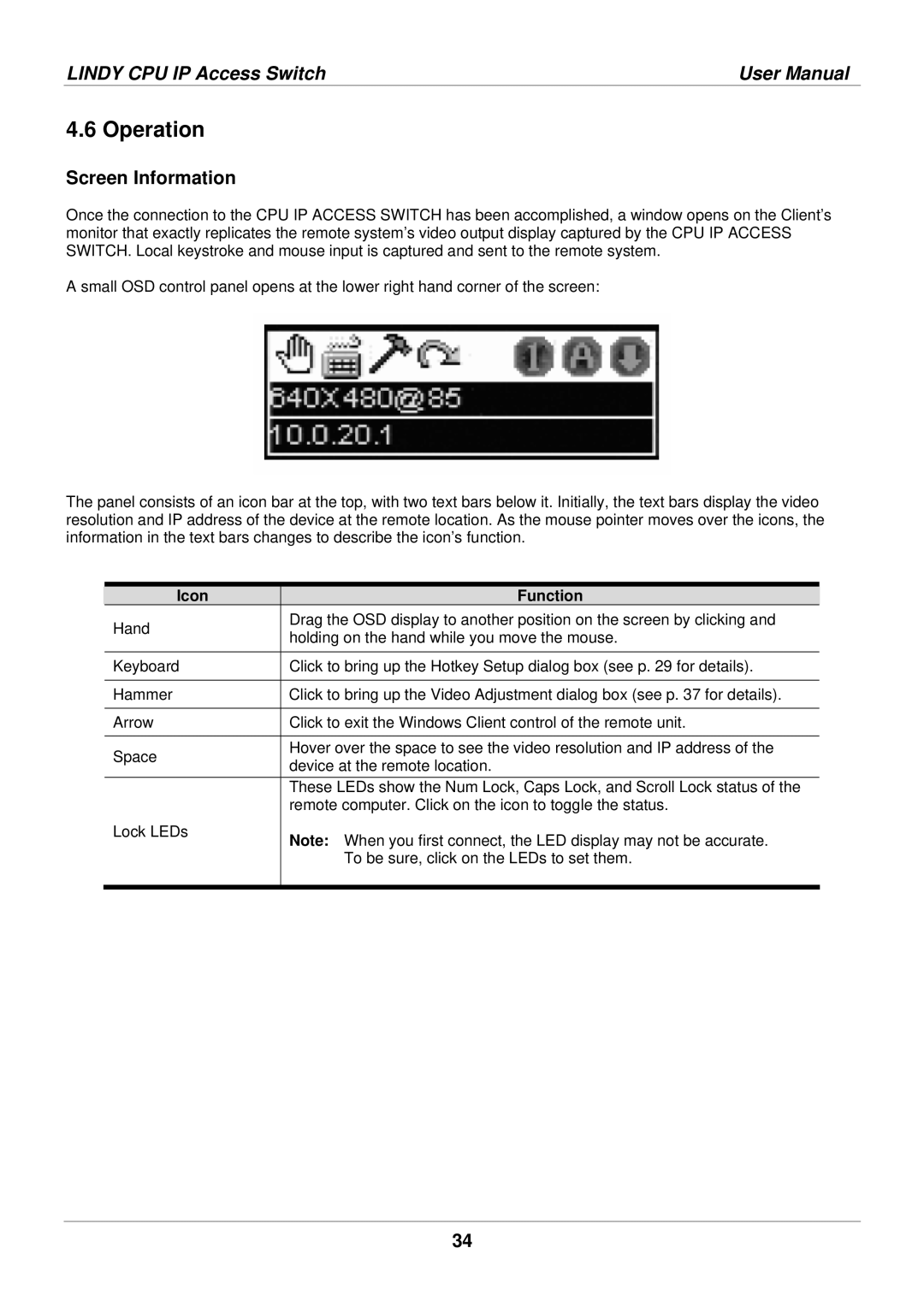
A small OSD control panel opens at the lower right hand corner of the screen:
The panel consists of an icon bar at the top, with two text bars below it. Initially, the text bars display the video resolution and IP address of the device at the remote location. As the mouse pointer moves over the icons, the information in the text bars changes to describe the icon’s function.
Icon | Function |
| |
Hand | Drag the OSD display to another position on the screen by clicking and | ||
holding on the hand while you move the mouse. | |||
| |||
|
|
| |
Keyboard | Click to bring up the Hotkey Setup dialog box (see p. 29 for details). | ||
|
|
| |
Hammer | Click to bring up the Video Adjustment dialog box (see p. 37 for details). | ||
|
|
| |
Arrow | Click to exit the Windows Client control of the remote unit. | ||
|
|
| |
Space | Hover over the space to see the video resolution and IP address of the | ||
device at the remote location. | |||
| |||
| These LEDs show the Num Lock, Caps Lock, and Scroll Lock status of the |
| |
| remote computer. Click on the icon to toggle the status. | ||
Lock LEDs | Note: When you first connect, the LED display may not be accurate. | ||
| |||
| To be sure, click on the LEDs to set them. | ||
|
|
| |
34