WebView Switches |
|
G1 | The |
| expansion module, so the Switch can be uplinked via fiber to another switch. Each |
| MiniGBIC port provides a link to a |
| speeds of up to 1000Mbps. |
| Use the Linksys MGBT1, MGBSX1, or MGBLH1 |
| MGBSX1 and the MGBLH1 require fiber cabling with LC connectors, while the MGBT1 |
| requires a Category 5e Ethernet cable with an |
9 | The 100LX port is where you can connect |
Console | The Console port is where you can connect a serial cable to a PC’s serial port for |
| configuration using your PC’s HyperTerminal program. Refer to Chapter 4: Using the |
| Console Interface for Configuration for more information. |
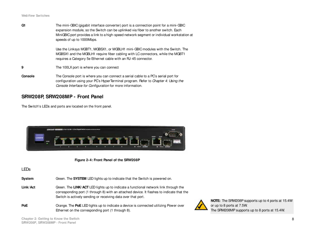
SRW208P, SRW208MP - Front Panel
The Switch's LEDs and ports are located on the front panel.
| Figure |
LEDs |
|
System | Green. The SYSTEM LED lights up to indicate that the Switch is powered on. |
Link/Act | Green. The LINK/ACT LED lights up to indicate a functional network link through the |
| corresponding port (1 through 8) with an attached device. It flashes to indicate that the |
| Switch is actively sending or receiving data over that port. |
PoE | Orange. The PoE LED lights up to indicate a device is connected utilizing Power over |
| Ethernet on the corresponding port (1 through 8). |
Chapter 2: Getting to Know the Switch
NOTE: The SRW208P supports up to 4 ports at 15.4W or up to 8 ports at 7.5W.
The SRW208MP supports up to 8 ports at 15.4W.
8
SRW208P, SRW208MP - Front Panel