CF-18
How to replace the fuse
For U.K This apparatus must be earthed for your safety
Laser Safety Information
Page
Page
Contents
Diagnosis Procedure
Basic Procedure
Troubleshooting
Table of errors classified by beep sounds
Error Diagnosis by Checking Beep Signal Sound
Outline of Post
Stuck key
02F4 Eisa Cmos not writable
Equipment
Preparation
Self Diagnosis Test
Vesa Mode Test
Speaker Test
CPU A20 Gate Test
Cache ON/OFF Test
LAN Test Modem Test Wireless LAN Test
Peripheral Test
Test Selection
End of test
Error Messages and Troubleshooting
Test classification Screen display test items Contents
Touch
PCB CN880
Screen Panel
Removing the Touch Pad and Key- board
Removing the Battery Pack and HDD Pack
HDD FPC
Removing the Speaker Angle and Dimm Lid
Removing the Rear Cabinet
KBD
FPC
Removing the DU Lid Unit Wireless Module Port PCB and Modem
Removing the Audio PCB
Removing the SD PCB
DU LID
Removing the Main PCB and Lith- ium Battery
Removing LED PCB and Switch
Removing the PAD PCB and I/O
Removing the CPU Heat Plate
Removing the LCD Hinge
Removing the Display unit Removing the LCD Rear Case
LCD
Removing Inverter PCB and LCD Removing the Each Cover Unit
Reassembly Instructions
Setting up the LCD Unit
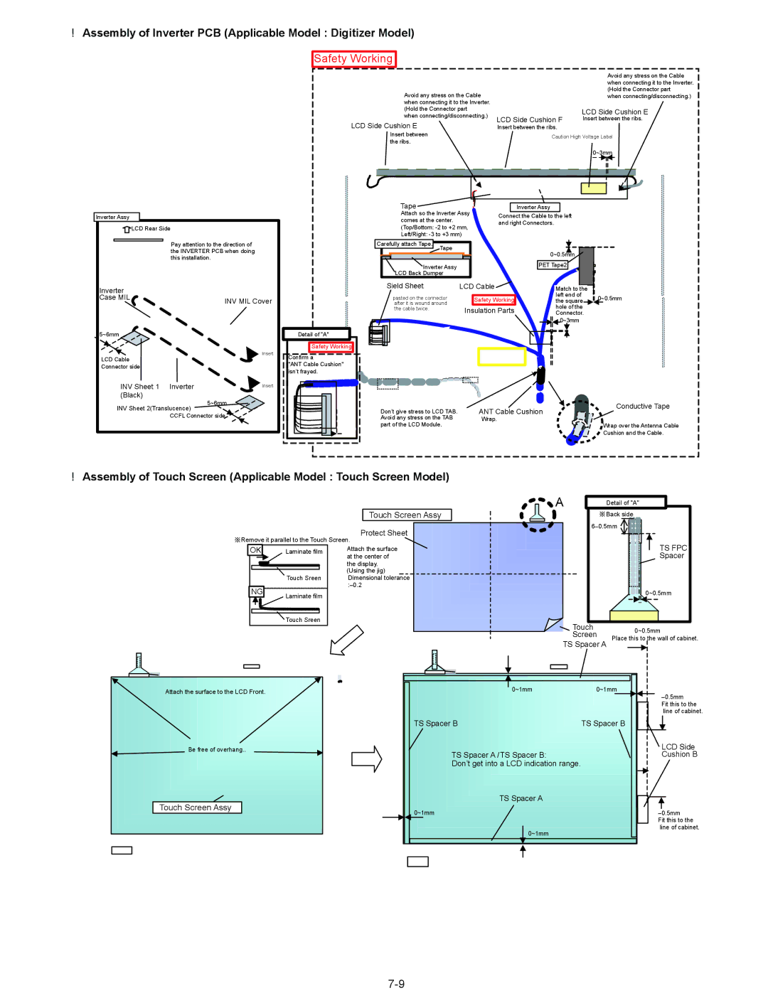
Safety Working
Assembly of Touch Screen Applicable Model Touch Screen Model
Touch Screen Assy
Assembly of Glass Applicable Model Digitizer Model
Glass Assy
Line processing of Antenna Cable
Gprs
Assembly of LCD Hinge
Setting up the LCD Hinge
Cable Hold Plate ScrewY
Line processing of Antenna Cable and LCD Cable
ANT Cable
HIinge Cover
LCD Cable
Assembly of LCD Front Case
Display Unit
Assembly of LCD Rear Case Applicable Model Digitizer Model
Assembly of Tablet Latch Cover and Antenna Cover
ANT Cover
Setting the Display Unit
Assembly of Display Unit
Setting the CPU Heat Plate
Modem Cable
Assembly of the LED PCB and the Switch PCB
Setting the LED PCB and the Switch PCB
PET Tape
Setting the PAD PCB and the I/O PCB
Assembly of PAD PCB
Assembly of TOP Case Assy
Putting of the PAD Insulation Sheet
Setting the Main PCB and the Lithium Battery
Line Processing of the Antenna Cable
Line Processing of the Lithium Battery
Pass the Lead Wire through the notch of the Board
Line Processing of Main Unit
CN3
Setting the SD PCB
Assembly of SD PCB
Setting the Wireless Module, the Port PCB, and the Modem
Assembly of the Port PCB
Line Processing of the Wireless Module,Port PCB and Modem
Cable
Screw
DU Sponge a
Setting the Audio PCB
Assembling the DU Lid Unit
Putting of the Sheet
Mm width x 5.5 cm
Setting the Rear Cabinet
Setting the Speaker and Dimm Lit
Displacement
Setting the Touch Pad and the Keyboard
LCD Cushion Sheet
KBD Waterproof Sheet R
KB CNT Hole
Cushion
Putting of the Palm Rest Assy
Keyboard KBD Tape
Screw Screw Screw
KBD PlateL Screw
Setting the Battery Pack and the HDD Pack
Assembly of the HDD Assy
Assembling the Each Cover
RGB
Exploded View
BT1
E42
K409
K210 K200-30 K211 K200-30-4 K200-30-35 K200-30-35-1
K220
Screw tightening torque
Wireless LAN Module
Description QTY
PCB, Main RTL
PCB, Audio RTL
DFJK13T024DB FFC, PAD
PCB, Wide Area AUX Antenna RTL
DFJS977ZA CABLE, Wide Area AUX ANT. Brown
DL3U7B482AAA PCB, SD RTL
DFHR3551YA Coin Battery Sheet
Power SW Knob
DFHR3262ZA Modem Tape
DFHR3301YA Mini PCI Card Sheet
TOP Case Assy
Tablet Latch Assy
Batt LID Assy
DFBH3030ZA LID Hinge
DFHR3477ZA Spacer B
DFHR3630ZA TS FPC Spacer
DFHR3674YA TS Tape
DL3DV0180AAA TS Panel Assy
DXYN2+J12FNL Screw
DXYN2+J18FNL Screw
DRHM0061ZA Screw
DXYN4+J8FNL Screw
RTC Battery
Main PCB
EEFCD0D151ER
Page
Page
Page
Page
EEFCD0D101ER
EEFCX0D331R
EEFCX0D221R
EEFUD0J151ER
EEFCX0J101R
Connector
EEFCX0G151R
EEFCD0G101ER
EEFCD0J470ER
IC, USB Power Control
DEDRB081L20 Diode
FUSE, 5A
FUSE, 2A
IC, Micon
IC, Regurator
IC, 1 Gate Logic
IC, Gate Logic DA2205IDBLET IC, Bipolar Logic
Poly SW
DDAZS100MT3T Inductor
Transistor
DETA144EETL Transistor
Transistor ERJ2GEJ681X
ERJ2RKF27R4X
ERJ2RKF54R9X
ERJ2RKF39R2X
ERJ2GE0R00X RESISTOR, 1/16W, 0Ω
ERJ2RKF80R6X RESISTOR, 1/16W
ERJ2GEJ103X RESISTOR, 1/16W
ERJ2GEJ222X
ERJ2GEJ101X
ERJ2RKF1002X RESISTOR, 1/16W, 10KΩ
Resistor Array ERJ2RKF1501X
ERJ2GEJ390X
ERJ2RKF2550X
ERJ2GEJ2R2X
ERJ2GEJ102X RESISTOR, 1/16W, 1KΩ
ERJ2RKF49R9X
ERJ2GEJ330X
ERJ2RKF4750X
ERJ2GEJ1R0X RESISTOR, 1/16W, 1Ω
ERJ2GEJ104X
ERJ2RKF22R6X
DEARA8AJ103M Resistor Array
ERJ2GEJ472X
ERJ2GEJ203X RESISTOR, 1/16W, 20KΩ
ERJ2GEJ473X RESISTOR, 1/16W, 47KΩ
ERJ2GEJ181X
ERJ2GEJ221X
ERJ2GEJ471X
ERJ2RKF1302X RESISTOR, 1/16W, 13KΩ
ERJ2GEJ474X
ERJ2RHD752X
ERJ2RKF2002X RESISTOR, 1/16W, 20KΩ
ERJ2RHD302X RESISTOR, 1/16W, 3KΩ
ERA3YKB104V
ERA3YEB333V RESISTOR, 1/16W, 33KΩ
Trance
IC, AC97 Codec
IC, Audio AMP
ERJ2GEJ103X RESISTOR, 1/16W, 1KΩ
ERJ2GEJ273X RESISTOR, 1/16W, 27KΩ
Connector DFJS830YA
EZASCE101M Capacitor Array
ERJ2RKF75R0X
IC, Flat PAD Controller
ERJ2GEJ822X
ERJ2GEJ103X RESISTOR, 1/16W, 10KΩ
EVQPLDA15
LED
ERJ2GEJ303X RESISTOR, 1/16W, 30KΩ
ERJ6GEYJ101V