INSTALLATION FOR OCIA INTERFACE (CONTINUED)
To power the unit from the host device:
(For OCIA only)
1.Follow the “Getting Started” steps on page 3.
2.Turn off the host system.
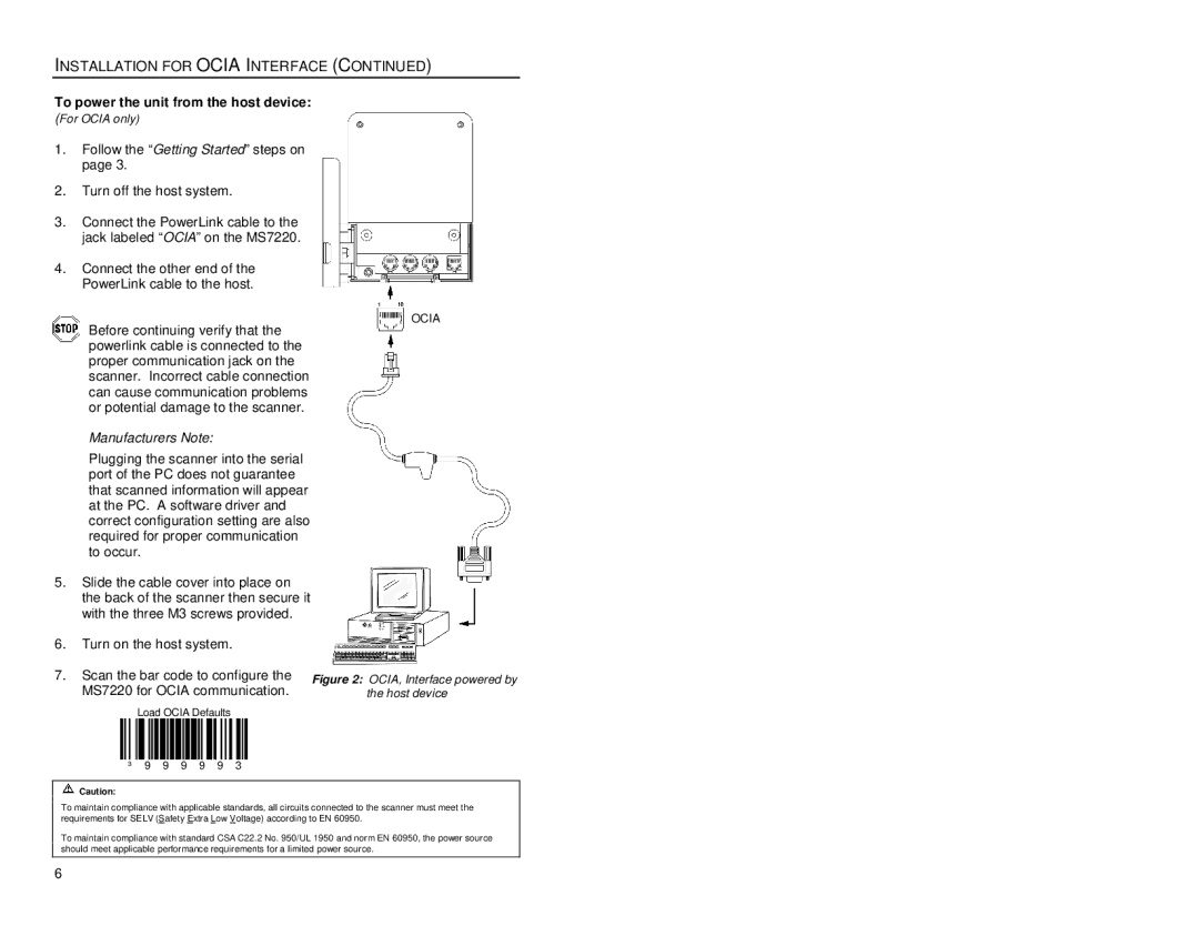
3.Connect the PowerLink cable to the jack labeled “OCIA” on the MS7220.
4.Connect the other end of the PowerLink cable to the host.
Before continuing verify that the powerlink cable is connected to the proper communication jack on the scanner. Incorrect cable connection can cause communication problems or potential damage to the scanner.
OCIA
Manufacturers Note:
Plugging the scanner into the serial port of the PC does not guarantee that scanned information will appear at the PC. A software driver and correct configuration setting are also required for proper communication to occur.
5.Slide the cable cover into place on the back of the scanner then secure it with the three M3 screws provided.
6.Turn on the host system.
7.Scan the bar code to configure the MS7220 for OCIA communication.
Load OCIA Defaults
³ 9 9 9 9 9 3
Figure 2: OCIA, Interface powered by the host device
![]() Caution:
Caution:
To maintain compliance with applicable standards, all circuits connected to the scanner must meet the requirements for SELV (Safety Extra Low Voltage) according to EN 60950.
To maintain compliance with standard CSA C22.2 No. 950/UL 1950 and norm EN 60950, the power source should meet applicable performance requirements for a limited power source.
6