INSTALLATION FOR OCIA INTERFACE
To power the unit with an external power supply:
1.Follow the “Getting Started” steps on page 3.
2.Turn off the host system.
3.Connect the PowerLink cable to the jack labeled “OCIA ” on the MS7220.
4.Connect the other end of the PowerLink cable to the host.
Before continuing verify that the
powerlink cable is connected to theOCIA proper communication jack on the
scanner. Incorrect cable connection can cause communication problems or potential damage to the scanner.
5.Connect the external power supply to the power jack on the Power Link Cable.
6.Check the AC input requirements of the power supply to make sure the voltage matches the AC outlet.
7.Connect AC power to the transformer. The outlet should be near the equipment and easily accessible.
8.Slide the cable cover into place on the back of the scanner then secure it with the three M3 screws provided.
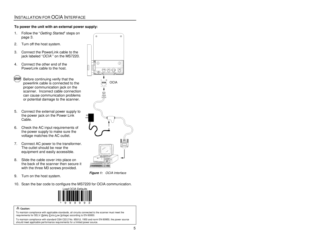
Figure 1: OCIA Interface
9.Turn on the host system.
10.Scan the bar code to configure the MS7220 for OCIA communication.
Load OCIA Defaults
³ 9 9 9 9 9 3
![]() Caution:
Caution:
To maintain compliance with applicable standards, all circuits connected to the scanner must meet the requirements for SELV (Safety Extra Low Voltage) according to EN 60950.
To maintain compliance with standard CSA C22.2 No. 950/UL 1950 and norm EN 60950, the power source should meet applicable performance requirements for a limited power source.
5