Metrologic Instruments MS7220 manual Cable Connector Configurations, “Standard” PowerLink cable

Models: MS7220

1 49
Download 49 pages 19.8 Kb
Page 44
Image 44
MS7220

SCANNER AND CABLE TERMINATIONS (CONTINUED)
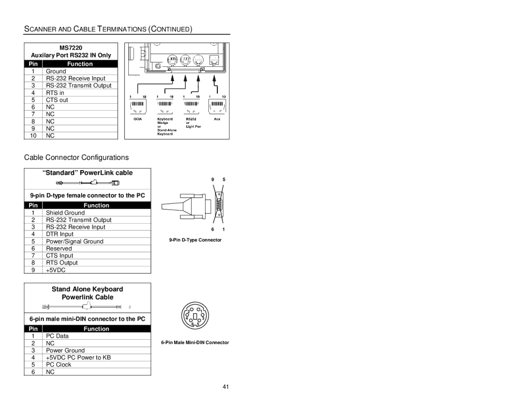
MS7220

Auxilary Port RS232 IN Only

Pin Function

1Ground

2RS-232 Receive Input

3RS-232 Transmit Output

4RTS in

5CTS out

6NC

7NC

8NC

9NC

10 NC

Cable Connector Configurations

“Standard” PowerLink cable

9-pin D-type female connector to the PC

PinFunction

1Shield Ground

2RS-232 Transmit Output

3RS-232 Receive Input

4DTR Input

5Power/Signal Ground

6Reserved

7CTS Input

8RTS Output

9+5VDC

Stand Alone Keyboard

Powerlink Cable

6-pin male mini-DIN connector to the PC

PinFunction

1PC Data

2NC

3Power Ground

4+5VDC PC Power to KB

5PC Clock

6NC

9 5

6 1

9-Pin D-Type Connector

Cable Connector Configurations2 1“Standard” PowerLink cable

4 9-pin D-type female connector to the PCPinFunction 3

6 5

6-Pin Male Mini-DIN Connector

41

Page 44
Image 44
Metrologic Instruments MS7220 manual Cable Connector Configurations, “Standard” PowerLink cable, Pin Function, PinFunction