GETTING STARTED
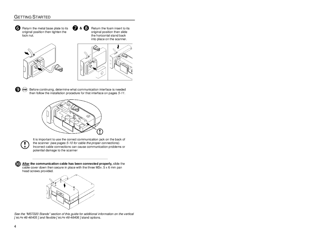
Return the metal base plate to its original position then tighten the lock nut.
Return the foam insert to its original position then slide the horizontal stand back into place on the scanner.
Before continuing, determine what communication interface is needed then follow the installation procedure for that interface on pages
It is important to use the correct communication jack on the back of the scanner (see pages
After the communication cable has been connected properly, slide the cable cover down then secure in place with the three M3x .5 x 6 mm pan head screws provided.
See the “MS7220 Stands” section of this guide for additional information on the vertical [ MLPN
4