Rear Panel
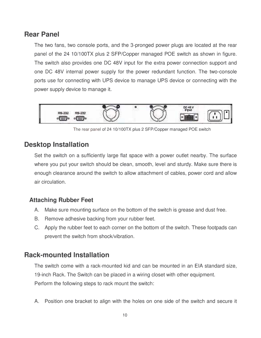
The two fans, two console ports, and the
The rear panel of 24 10/100TX plus 2 SFP/Copper managed POE switch
Desktop Installation
Set the switch on a sufficiently large flat space with a power outlet nearby. The surface where you put your switch should be clean, smooth, level and sturdy. Make sure there is enough clearance around the switch to allow attachment of cables, power cord and allow air circulation.
Attaching Rubber Feet
A.Make sure mounting surface on the bottom of the switch is grease and dust free.
B.Remove adhesive backing from your rubber feet.
C.Apply the rubber feet to each corner on the bottom of the switch. These footpads can prevent the switch from shock/vibration.
Rack-mounted Installation
The switch come with a
Perform the following steps to rack mount the switch:
A.Position one bracket to align with the holes on one side of the switch and secure it
10