.A complete Parts List is available at www.MillerWelds.com
6-3. Typical Stick Welding Connections And Control Settings
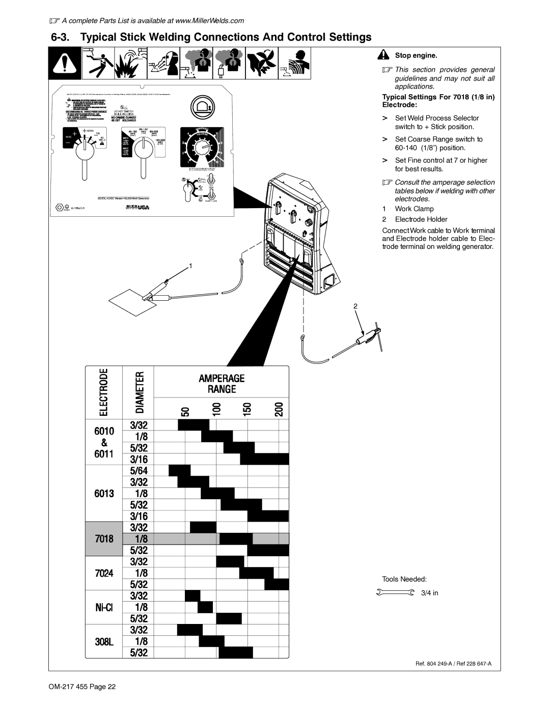
! Stop engine.
. This section provides general guidelines and may not suit all applications.
Typical Settings For 7018 (1/8 in)
Electrode:
> Set Weld Process Selector switch to + Stick position.
> Set Coarse Range switch to
> Set Fine control at 7 or higher for best results.
. Consult the amperage selection tables below if welding with other electrodes.
1 Work Clamp
2 Electrode Holder
Connect Work cable to Work terminal and Electrode holder cable to Elec- trode terminal on welding generator.
1
2
Tools Needed: 3/4 in
Ref. 804