Manuals
/
Miller Electric
/
Power Tools
/
Welder
Miller Electric
250
manual
804 197-A / Ref 803 111-A / 227
Models:
250
1
37
72
72
Download
72 pages
35.83 Kb
34
35
36
37
38
39
40
41
Troubleshooting
Specs
Poor Weld Bead Characteristics
Install
Parts list
Electrical Diagrams
Symbol Usage
Service Indicator Optional
Welding Wire can cause injury
Dimension
Page 37
Image 37
.
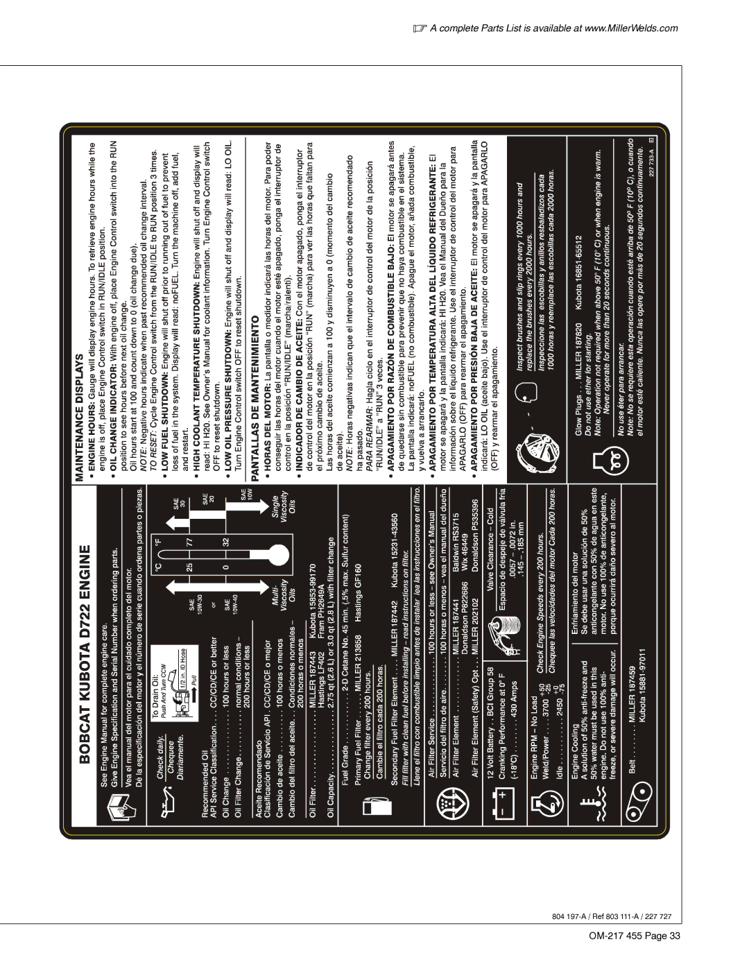
A complete Parts List is available at www.MillerWelds.com
804
197-A /
Ref 803
111-A /
227 727
OM-217
455 Page 33
Page 36
Page 38
Page 37
Image 37
Page 36
Page 38
Contents
File Engine Drive
OM-217 455H
Visit our website at
2007−05−21
From Miller to You
Table of Contents
13-3
13-2
13-4
13-5
Arc Welding Hazards
Symbol Usage
Electric Shock can kill
HOT Parts can cause severe burns
Buildup of GAS can injure or kill
Fumes and Gases can be hazardous
ARC Rays can burn eyes and skin
Welding can cause fire or explosion
Compressed Air Hazards
Engine Hazards
HOT Parts can cause burns and injury
Welding Wire can cause injury
Fire or Explosion hazard
Falling Unit can cause injury
California Proposition 65 Warnings
Principal Safety Standards
EMF Information
Radiation can cause interference
− Consignes DE Sécurité − Lire Avant Utilisation
Signification des symboles
UN Choc Électrique peut tuer
Indique des instructions spécifiques
LES Fumées ET LES GAZ peuvent être dangereux
DES Pièces Chaudes peuvent provoquer des brûlures graves
LE Soudage peut provoquer un in cendie ou une explosion
’EXPLOSION DE LA Batterie peu
LE Bruit peut affecter l’ouïe
DES Organes Mobiles peuvent pro voquer des blessures
’AIR Comprimé peut provoquer des blessures
LA Chaleur DU Moteur peut pro- voquer un incendie
Risque D’INCENDIE OU D’EXPLO- Sion
DES Organes Mobiles peuvent provoquer des blessures
LE Surchauffement peut endom- mager le moteur électrique
LES Fils DE Soudage peuvent provoquer des blessures
’EMPLOI Excessif peut
Principales normes de sécurité
Proposition californienne 65 Avertissements
Information EMF
En ce qui concerne les implants médicaux
Symbol Definitions
− Specifications
Weld, Power, and Engine Specifications
− Definitions
Dimensions For Units With Optional Running Gear
Dimensions, Weights, and Operating Angles
Dimensions
Installing Welding Generator
− Installation
Vehicle frame. Always connect a ground wire
Mounting
Connecting the Battery
Installing Exhaust Pipe
+ −
Stop engine and let cool
Overview And Engine Prestart Checks
Starting engine for the first time
Engine Left Side Engine Right Side
Run-in period first 100 hours
Daily pre-start checks
Correct Installation
Connecting to Weld Output Terminals
Work Weld Output Terminal
Tools Needed Do not place
Selecting Weld Cable Sizes
Place switch in Run position to operate most MIG equipment
Engine Control Switches
− Operating the Welding Generator
Do not use glow plugs longer than 20 seconds
Weld Output Controls
Typical Settings For 7018 1/8 Electrode
Typical Stick Welding Connections And Control Settings
Stop engine
Work Clamp Electrode Holder
Set Weld Process Selector switch to Wire + Dcep position
Typical MIG Welding Connections And Settings
Set Weld Process Selector switch to Wire + position
Set Weld Process Selector switch to Wire − position Dcen
Tools Needed 3/4 Work Not Used To Work Left Side View
− Operating Auxiliary Equipment
Generator Power Receptacles
At least once a month, run engine at
To verify Gfci is working properly
Simultaneous Weld And Power
Battery Charge Controls
− Operating Optional Battery Charger
Determining Battery Charging Current
Battery Charge Cable Connections
Minutes
Battery Charging Procedure
Start Your Professional Welding Career Now
Routine Maintenance
− Maintenance and Troubleshooting
Stop engine and let cool Oil And Fuel
Maintenance Label And Engine Maintenance Activities
804 197-A / Ref 803 111-A / 227
Ment is not covered by the warranty
Cleaner or with dirty element. Engine
Air cleaner primary element can
Damage when determining whether
Adjusting Fuel Solenoid Position
Adjusting Engine Speed
Stop screw is factory-set and should not be adjusted
Checking Fuel Solenoid
Checking Throttle Solenoid
Adjusting Throttle Solenoid
16 mm
Check for non-binding
Adjusting Idle Speed
Making Engine Speed Adjustments
Adjusting Weld/Power Speed
Component Panel Stop engine
Overload Protection
Fuse F1
Supplementary Protector CB8
Generator Power
Troubleshooting Tables
Welding
Trouble Remedy
Engine
Maintenance Display Action
Recommended Spare Parts
− Parts List
Recommended Spare Parts
Current transformer CT1, and throttle solenoid TS1
Circuit Diagram For Welding Generator
− Electrical Diagrams
228 719-B
OM-217 455
231 607-B
Run-In And Wetstacking
− RUN-IN and Wetstacking
Fuel Consumption Curves
− Performance Data
US Gal./Hr
Idle
Duty Cycle
Generator Power Curve
Volts
AC Amperes At 120 Volts
DC Amps CC/AC Stick Mode AC Volts
Stick Mode Volt-Ampere Curves
AC Amps
DC Amps
MIG Mode Volt-Ampere Curve
Selecting Equipment
− Generator Power Guidelines
Grounding Generator To Truck Or Trailer Frame
How Much Power Does Equipment Require?
Grounding When Supplying Building Systems
Use ground device as stated in electrical codes
Amperes x Volts = Watts
Approximate Power Requirements For Farm/Home Equipment
Approximate Power Requirements For Industrial Motors
Industrial Motors Rating Starting Watts Running Watts
Farm/Home Equipment Rating Starting Watts Running Watts
Contractor Rating Starting Watts Running Watts
Approximate Power Requirements For Contractor Equipment
How Much Power Can Generator Supply?
Power Required To Start Motor
Single-Phase Induction Motor Starting Requirements
KVA/HP x HP x 1000 / Volts = Starting Amperage
Typical Connections To Supply Standby Power
Selecting Extension Cord Use Shortest Cord Possible
Weld current starts when electrode touches work- piece
Stick Welding Procedure
− Stick Welding Smaw Guidelines
Striking an Arc − Scratch Start Technique
Electrode and Amperage Selection Chart
Striking an Arc − Tapping Technique
Good Weld Bead Characteristics
Poor Weld Bead Characteristics
Positioning Electrode Holder
10-30 9090 End View of Work Angle
Electrode Movement During Welding
Conditions That Affect Weld Bead Shape
Lap Joint
Butt Joints
Tee Joint
16 in 30 1.6 mm Tack Welds
Troubleshooting − Excessive Spatter
Troubleshooting − Porosity
Weld Test
Possible Causes Corrective Actions
Troubleshooting − Lack Of Penetration
Troubleshooting − Incomplete Fusion
Troubleshooting − Excessive Penetration
Troubleshooting − Waviness Of Bead
Troubleshooting − Burn-Through
Troubleshooting − Distortion
Work like a Pro
Your distributor also gives
Service
Support
Miller Electric Mfg. Co
To locate a Distributor or Service Agency visit
For assistance in filing or settling claims, contact
Your distributor and/or equipment manufacturer’s
Top
Page
Image
Contents