. A complete Parts List is available at www.MillerWelds.com
C. Making Engine Speed Adjustments
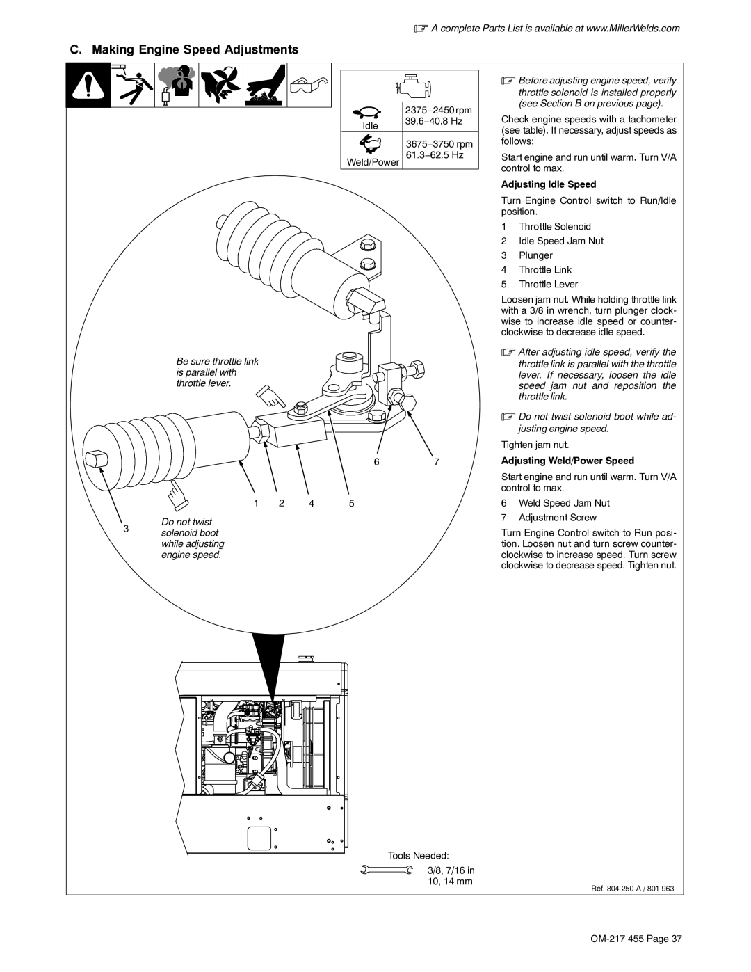
| 2375−2450 rpm |
Idle | 39.6−40.8 Hz |
| |
| 3675−3750 rpm |
Weld/Power 61.3−62.5 Hz | |
Be sure throttle link is parallel with throttle lever.
67
1 | 2 | 4 | 5 |
Do not twist
3 solenoid boot while adjusting engine speed.
.Before adjusting engine speed, verify
throttle solenoid is installed properly (see Section B on previous page).
Check engine speeds with a tachometer (see table). If necessary, adjust speeds as follows:
Start engine and run until warm. Turn V/A control to max.
Adjusting Idle Speed
Turn Engine Control switch to Run/Idle position.
1Throttle Solenoid
2Idle Speed Jam Nut
3Plunger
4Throttle Link
5Throttle Lever
Loosen jam nut. While holding throttle link with a 3/8 in wrench, turn plunger clock- wise to increase idle speed or counter- clockwise to decrease idle speed.
.After adjusting idle speed, verify the
throttle link is parallel with the throttle lever. If necessary, loosen the idle speed jam nut and reposition the throttle link.
.Do not twist solenoid boot while ad- justing engine speed.
Tighten jam nut.
Adjusting Weld/Power Speed
Start engine and run until warm. Turn V/A control to max.
6Weld Speed Jam Nut
7Adjustment Screw
Turn Engine Control switch to Run posi- tion. Loosen nut and turn screw counter- clockwise to increase speed. Turn screw clockwise to decrease speed. Tighten nut.
Tools Needed:
3/8, 7/16 in 10, 14 mm
Ref. 804