.A complete Parts List is available at www.MillerWelds.com
SECTION 3 − DEFINITIONS
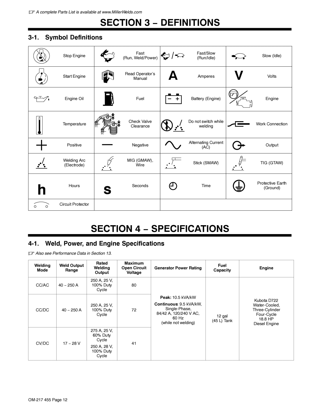
3-1. Symbol Definitions
| Stop Engine |
| Fast |
| Fast/Slow |
| Slow (Idle) |
|
| (Run, Weld/Power) |
| (Run/Idle) |
| ||
|
|
|
|
|
| ||
| Start Engine |
| Read Operator’s | A | Amperes | V | Volts |
|
| Manual | |||||
|
|
|
|
| |||
| Engine Oil |
| Fuel |
| Battery (Engine) |
| Engine |
| Temperature |
| Check Valve |
| Do not switch while |
| Work Connection |
|
| Clearance |
| welding |
| ||
|
|
|
|
|
| ||
| Positive |
| Negative |
| Alternating Current |
| Output |
|
|
| (AC) |
| |||
|
|
|
|
|
|
| |
| Welding Arc |
| MIG (GMAW), |
| Stick (SMAW) |
| TIG (GTAW) |
| (Electrode) |
| Wire |
|
| ||
|
|
|
|
|
| ||
h | Hours | s | Seconds |
| Time |
| Protective Earth |
|
|
|
| (Ground) | |||
|
|
|
|
|
|
| |
| Circuit Protector |
|
|
|
|
|
|
SECTION 4 − SPECIFICATIONS
4-1. Weld, Power, and Engine Specifications
.Also see Performance Data in Section 13.
Welding | Weld Output | Rated | Maximum |
| Fuel |
| |
Welding | Open Circuit | Generator Power Rating | Engine | ||||
Mode | Range | Capacity | |||||
Output | Voltage |
|
| ||||
|
|
|
|
| |||
|
|
|
|
|
|
| |
|
| 250 A, 25 V, |
|
|
|
| |
CC/AC | 40 − 250 A | 100% Duty | 80 |
|
|
| |
|
| Cycle |
|
|
|
| |
|
|
|
| Peak: 10.5 kVA/kW |
| Kubota D722 | |
|
|
|
|
| |||
|
|
|
| Continuous: 9.5 kVA/kW, |
| ||
|
| 250 A, 25 V, |
|
| |||
CC/DC | 40 − 250 A | 100% Duty | 72 |
| |||
|
| Cycle |
| 84/42 A, 120/240 V AC, | 12 gal | ||
|
|
|
| 60 Hz | 18.8 HP | ||
|
|
|
| (45 L) Tank | |||
|
|
|
| (while not welding) | Diesel Engine | ||
|
|
|
|
| |||
|
|
|
|
|
|
| |
|
| 275 A, 25 V, |
|
|
|
| |
|
| 60% Duty |
|
|
|
| |
CV/DC | 17 − 28 V | Cycle | 41 |
|
|
| |
250 A, 28 V, |
|
|
| ||||
|
|
|
|
|
| ||
|
| 100% Duty |
|
|
|
| |
|
| Cycle |
|
|
|
| |
|
|
|
|
|
|
|