. A complete Parts List is available at www.MillerWelds.com
SECTION 8 − OPERATING OPTIONAL BATTERY CHARGER
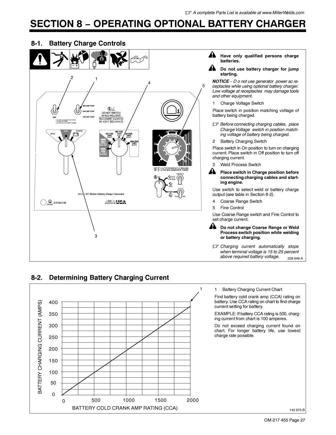
8-1. Battery Charge Controls
|
|
| ! | Have only qualified persons charge | |
|
|
|
| batteries. |
|
|
|
| ! | Do not use battery charger for jump | |
2 | 1 |
|
| starting. |
|
| NOTICE − D o not use generator power ac re- | ||||
| 4 | 5 | |||
| ceptacles while using optional battery charger. | ||||
|
| ||||
|
|
| Low voltage at receptacles may damage tools | ||
|
|
| and other equipment. |
| |
|
|
| 1 | Charge Voltage Switch |
|
|
|
| Place switch in position matching voltage of | ||
|
|
| battery being charged. |
| |
|
|
| . Before connecting charging cables, place | ||
|
|
|
| Charge Voltage switch in position match- | |
|
|
|
| ing voltage of battery being charged. | |
|
|
| 2 | Battery Charging Switch |
|
|
|
| Place switch in On position to turn on charging | ||
|
|
| current. Place switch in Off position to turn off | ||
|
|
| charging current. |
| |
|
|
| 3 | Weld Process Switch |
|
|
|
| ! | Place switch in Charge position before | |
|
|
|
| connecting charging cables and start- | |
|
|
|
| ing engine. |
|
|
|
| Use switch to select weld or battery charge | ||
|
|
| output (see table in Section |
| |
|
|
| 4 | Coarse Range Switch |
|
|
|
| 5 | Fine Control |
|
|
|
| Use Coarse Range switch and Fine Control to | ||
|
|
| set charge current. |
| |
|
|
| ! | Do not change Coarse Range or Weld | |
| 3 |
|
| Process switch position while welding | |
|
|
| or battery charging. |
| |
|
|
|
|
| |
|
|
| . Charging current automatically stops | ||
|
|
|
| when terminal voltage is 15 to 25 percent | |
|
|
|
| above required battery voltage. | 228 |
|
|
|
|
| |
8-2. Determining Battery Charging Current
1
(AMPS) | 400 |
|
|
|
|
350 |
|
|
|
| |
CURRENT | 300 |
|
|
|
|
250 |
|
|
|
| |
|
|
|
|
| |
CHARGING | 200 |
|
|
|
|
150 |
|
|
|
| |
100 |
|
|
|
| |
BATTERY |
|
|
|
| |
50 |
|
|
|
| |
0 |
|
|
|
| |
| 500 | 1000 | 1500 | 2000 | |
| 0 |
BATTERY COLD CRANK AMP RATING (CCA)
1 Battery Charging Current Chart
Find battery cold crank amp (CCA) rating on battery. Use CCA rating on chart to find charge current setting for battery.
EXAMPLE: If battery CCA rating is 500, charg- ing current from chart is 100 amperes.
Do not exceed charging current found on chart. For longer battery life, use lowest charge rate possible.
142