.A complete Parts List is available at www.MillerWelds.com
B.Checking Throttle Solenoid
1 2 3 5
4
6
5/8 in (16 mm)
7 |
| Check for |
| movement of link with sole- | |
|
| |
|
| noid in energized position. |
|
|
|
|
|
|
 ! Stop engine.
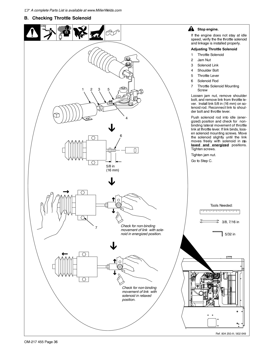
If the engine does not stay at idle speed, verify the the throttle solenoid and linkage is installed properly.
Adjusting Throttle Solenoid
1Throttle Solenoid
2Jam Nut
3Solenoid Link
4Shoulder Bolt
5Throttle Lever
6Solenoid Rod
7Throttle Solenoid Mounting Screw
Loosen jam nut, remove shoulder bolt, and remove link from throttle le- ver. Install link 5/8 in (16 mm) on so- lenoid rod. Reconnect link to shoul- der bolt and throttle lever.
Push solenoid rod into idle (ener- gized) position and check for non- binding lateral movement of throttle link at throttle lever. If link binds, loos- en solenoid mounting screws. Move the solenoid slightly until the link moves freely with solenoid in re- laxed and energized positions. Tighten screws.
Tighten jam nut. Go to Step C.
Tools Needed:
3/8, 7/16 in
![]() 5/32 in
5/32 in
Check for
Ref. 804
