.A complete Parts List is available at www.MillerWelds.com
Tools Needed: 3/4 in
9
8
Work
6
2
10
12
Not Used | 5 |
| |
To Work |
|
Left Side View
11
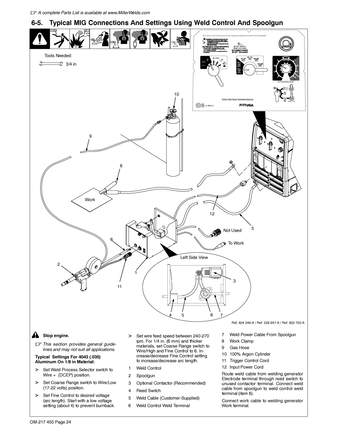
 ! Stop engine.
.This section provides general guide- lines and may not suit all applications.
Typical Settings For 4043 (.035) Aluminum On 1/8 in Material:
>Set Weld Process Selector switch to Wire + (DCEP) position.
>Set Coarse Range switch to Wire/Low
>Set Fine Control to desired voltage (arc length). Start with a low voltage setting (about 4) to prevent burnback.
1
4 | 5 | 6 |
>Set wire feed speed between
1Weld Control
2Spoolgun
3Optional Contactor (Recommended)
4Reed Switch
5Weld Cable
6Weld Control Weld Terminal
3
7
Ref. 804
7Weld Power Cable From Spoolgun
8Work Clamp
9Gas Hose
10100% Argon Cylinder
11Trigger Control Cord
12Input Power Cord
Route weld cable from welding generator Electrode terminal through reed switch to unused contactor terminal. Connect weld cable from spoolgun to weld control weld terminal (item 6).
Connect work cable to welding generator Work terminal.