.A complete Parts List is available at www.MillerWelds.com
SECTION 6 − OPERATING THE WELDING GENERATOR
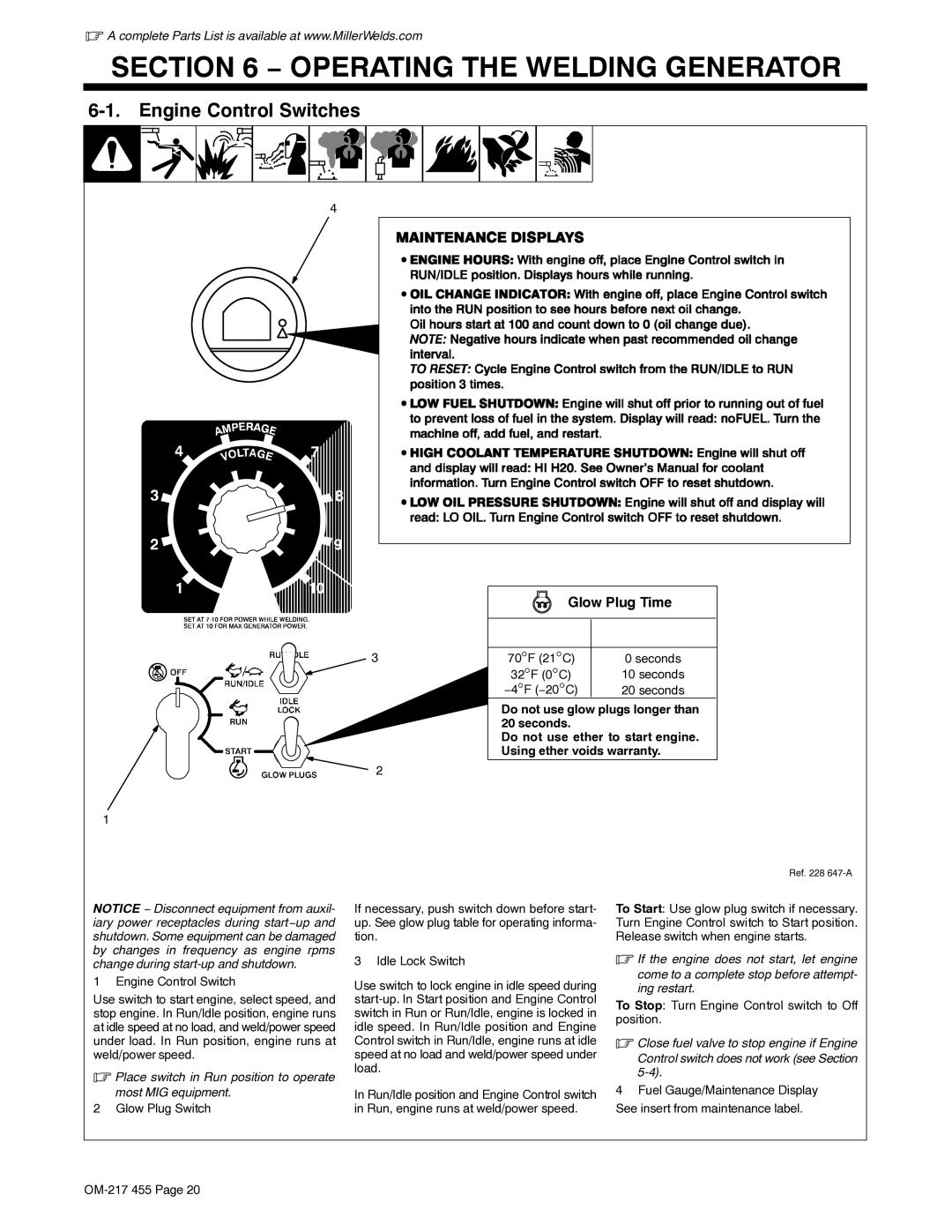
6-1. Engine Control Switches
4
3
2
Glow Plug Time
|
|
|
|
|
|
|
|
|
|
|
|
|
|
|
| t | |
|
|
|
|
|
| |||
|
|
| 70°F (21°C) | 0 seconds | ||||
|
|
| 32°F (0°C) |
|
| 10 seconds | ||
|
| −4°F (−20°C) |
|
|
| 20 seconds | ||
Do not use glow plugs longer than 20 seconds.
Do not use ether to start engine. Using ether voids warranty.
1
Ref. 228
NOTICE − Disconnect equipment from auxil- iary power receptacles during start−up and shutdown. Some equipment can be damaged by changes in frequency as engine rpms change during
1 Engine Control Switch
Use switch to start engine, select speed, and stop engine. In Run/Idle position, engine runs at idle speed at no load, and weld/power speed under load. In Run position, engine runs at weld/power speed.
.Place switch in Run position to operate most MIG equipment.
2 Glow Plug Switch
If necessary, push switch down before start- up. See glow plug table for operating informa- tion.
3 Idle Lock Switch
Use switch to lock engine in idle speed during
In Run/Idle position and Engine Control switch in Run, engine runs at weld/power speed.
To Start: Use glow plug switch if necessary. Turn Engine Control switch to Start position. Release switch when engine starts.
.If the engine does not start, let engine
come to a complete stop before attempt- ing restart.
To Stop: Turn Engine Control switch to Off position.
.Close fuel valve to stop engine if Engine
Control switch does not work (see Section
4Fuel Gauge/Maintenance Display See insert from maintenance label.