.A complete Parts List is available at www.MillerWelds.com
6-4. Typical MIG Welding Connections And Settings
6
7
2
3
5 ![]()
![]() 4
4
Work
1
Tools Needed: 3/4 in
 ! Stop engine.
.This section provides general guide-
lines and may not suit all ap- plications.
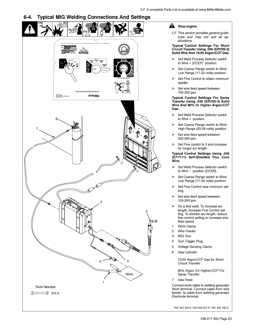
Typical Control Settings For Short Circuit Transfer Using .035
>Set Weld Process Selector switch to Wire + (DCEP) position.
>Set Coarse Range switch to Wire/ Low Range
>Set Fine Control to obtain minimum spatter.
>Set wire feed speed between
Typical Control Settings For Spray
Transfer Using .035
Wire And 80% Or Higher Argon/CO2
Gas:
>Set Weld Process Selector switch to Wire + position.
>Set Coarse Range switch to Wire/ High Range
>Set wire feed speed between
>Set Fine control to 3 and increase for longer arc length.
Typical Control Settings Using .045
Wire:
>Set Weld Process Selector switch to Wire − position (DCEN).
>Set Coarse Range switch to Wire/ Low Range
>Set Fine Control near minimum set- ting.
>Set wire feed speed between
>Do a test weld. To increase arc length, increase Fine Control set- ting. To shorten arc length, reduce fine control setting or increase wire feed speed.
1Work Clamp
2Wire Feeder
3MIG Gun
4Gun Trigger Plug
5Voltage Sensing Clamp
6Gas Cylinder:
75/25 Argon/CO2 Gas for Short Circuit Transfer
80% Argon (Or Higher)/CO2 For Spray Transfer
7Gas Hose
Connect work cable to welding generator Work terminal. Connect cable from wire feeder to cable from welding generator Electrode terminal.
Ref. 804